Vermes MDS 358X user Manual.pdf - 第71页
Initial Operation 60 VTK - TR -BA- 072e - 1 - User Manua l MDS 358X S eries – Confirm the adjus t with press ing [EN TER ] . The adjust is finished successfully and you are send back to the main me nu. Fig. 46 : Adjust –…
Initial Operation
VTK-TR-BA-072e-1 - User Manual MDS 358X Series
59
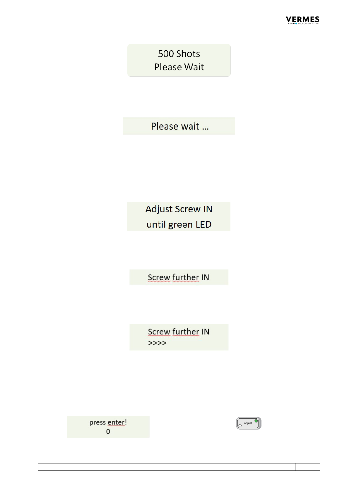
Fig. 40: Message 500 Shots – Please Wait
A few seconds later, the display shows the message “Please wait …”.
Fig. 41: Message Please wait …
Wait until a new message on the display announces the next step.
Adjust, step 2 (Turn in adjust screw):
The screen shows the message “Adjust Screw IN until green LED”.
Fig. 42: Message Adjust Screw IN – until green LED
After one second, the initial message disappears from the display. Instead, the message “Screw
further IN” appears.
Fig. 43: Message Screw further IN
– Screw the adjust screw carefully clockwise. While screwing, you will see an increasing amount
of arrows shown in the display (see Fig. 44).
Fig. 44: Arrows displayed
Adjust, step 3 (Find adjust point and confirm it):
– Keep turning the adjust screw slowly clockwise, until the display shows “press enter! - 0”.
Meanwhile, the green adjust LED is ON (see Fig. 45).
Fig. 45: Message press enter! – 0, the green adjust LED is ON
Initial Operation
60
VTK-TR-BA-072e-1 - User Manual MDS 358X Series
– Confirm the adjust with pressing [ENTER]. The adjust is finished successfully and you are send
back to the main menu.
Fig. 46: Adjust – Press Enter
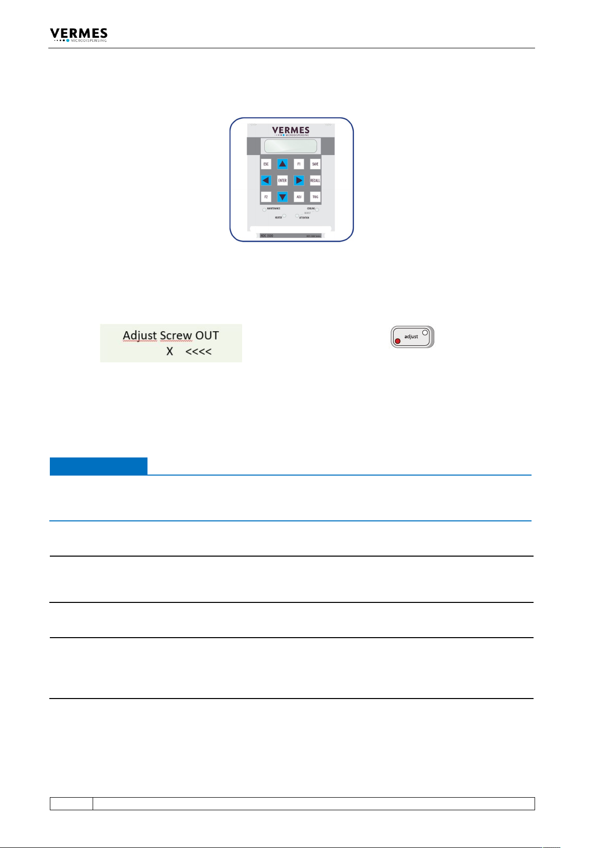
In case you had turned the adjust screw too far, the display shows “Adjust Screw OUT – X <<<<”.
Also, the red adjust LED is ON instead of the green one (see Fig. 47).
Fig. 47: Message Adjust Screw OUT – X <<<<, the red adjust LED is ON
– Unscrew the adjust screw (counter-clockwise) until the display shows “press enter! - 0” and
the green adjust LED is ON.
– Press the [ENTER]-key.
IMPORTANT NOTE
Do not screw too far
Do not keep screwing the adjust screw further clockwise, if the red adjust LED is ON. Otherwise
the tappet or the nozzle insert could get damaged.
INFORMATION
Confirming adjust
A correctly completed adjust can only be confirmed with [ENTER], while the green adjust LED is
ON.
INFORMATION
Abort and end of procedure
• The adjust can be aborted any time by pressing [ESC]. The display changes back to the main
menu.
• After the adjust the green lamp dims within approx. 3 s.
Initial Operation
VTK-TR-BA-072e-1 - User Manual MDS 358X Series
61
6.6 Initial Liquid Supply
– Step 1: If not using a prefilled cartridge, fill an empty one with the required fluid, till up to
80 % of its capacity.
– Step 2: Insert the cartridge into the corresponding holder and screw it onto the Luer-Lock
connector, rotating clockwise.
– Step 3: Place the compressed-air adaptor onto the cartridge and rotate clockwise until it
latches in place.
– Step 4: Connect the PVC hose with coupler plug KS4-CK-6 to air supply. A coupler socket type
KD4-1/2-A is required.
– Step 5: After establishing a convenient dispensing pressure, activate the pneumatic supply.
IMPORTANT NOTE
Check for leakage
All of the parts must be installed correctly, and the entire configuration must be leak-tight –
otherwise the dispensing fluid can trickle out in an uncontrolled manner.
Valves designed by VERMES Microdispensing can be operated at a relatively low supply pressure,
in the range between 0 bar and 7 bar. This upper limit should not be exceeded in normal
applications; in most cases, even a value of 4 bar is sufficient.
Standard values:
• Low-viscous fluids (e.g. water): 0.5 – 1.5 bar
• Medium viscosity (e.g. SMT-adhesives): 1.5 – 2.0 bar
• High viscosity (e.g. pastes): 2.0 – 7.0 bar
IMPORTANT NOTE
Do not activate system without dispensing medium
Except for the adjust, do not activate the system “dry” (i.e. without dispensing medium).
Otherwise, it might damage the system. For flushing the valve keep within the following limits:
• Needle Lift max. 80
• Falling min. 0.13
6.7 Removing Air Inclusions from the Fluid Box
Air must be removed from the fluid box, for instance after the exchange of a cartridge.
Save the current dispensing parameters beforehand (see paragraph 7.6, page 67).
Confirm the following parameter selection:
Rising 0.5, Open Time 1.5, Falling 0.17, Delay 5–30, Needle Lift 75, Number of Pulses 500–2000
Dispense a quantity of ca. 500 to 2000 shots by pressing [trig].
When this measure is complete, retrieve the initial parameters stored beforehand (see
paragraph 7.7, page 67) and start the dispensing process.