Vermes MDS 358X user Manual.pdf - 第59页
Initial Operation 48 VTK - TR -BA- 072e - 1 - User Manua l MDS 358X S eries Step 10 (fluid box) Turn t he locking lever b y 180° from “Close” t o “Op en” posit ion . Push t he flui d box c a refully i n a 45° ang le onto…
Initial Operation
VTK-TR-BA-072e-1 - User Manual MDS 358X Series
47
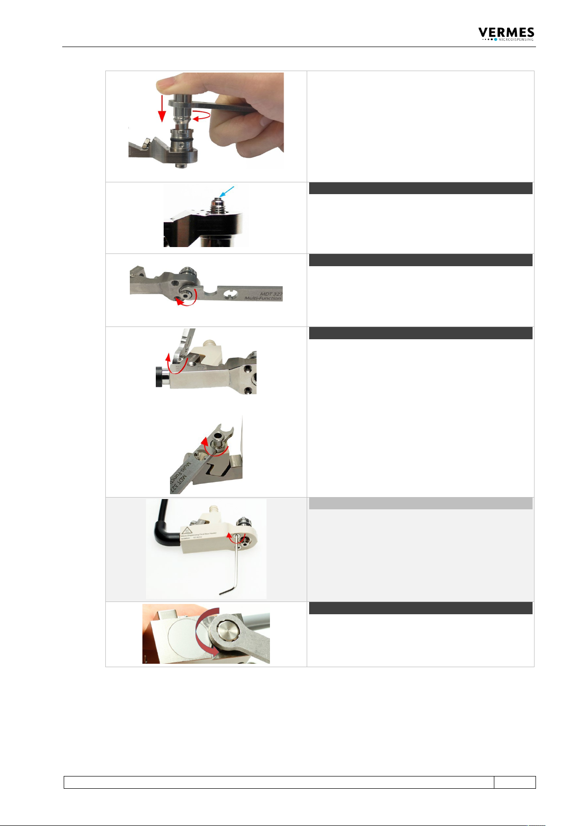
Screw the Tappet Centering Screw BY completely into
the fluid box (torque 100 – 140 cN.m) with MDT 303 -
Nozzle Insert Changing Tool.
Make sure the three pins of the MDT 303 fit exactly
into the three holes of the Tappet Centering Screw
BY. Turn the MDT 303 clockwise while pressing it
down slightly to the fluid box.
Combine the MDT 303 with MDT 327 for a better
leverage.
Step 6 (nozzle insert)
Clip the nozzle insert into the fluid box. Use the small
hole of MDT 327 - Multi-Function Tool to pick up the
nozzle insert and to place it. Make sure the nozzle
insert sits flat.
Step 7 (nozzle fixation nut)
Screw the nozzle fixation nut clockwise onto the fluid
box. Use MDT 327 Multi-Function Tool.
Step 8 (cartridge base)
Place the cartridge base onto the fluid box and fix it
with the tightening screw. Screw the tightening screw
clockwise with MDT 327 Multi-Function Tool (torque
120 – 140 cN.m).
Important note!
In case you use a Cartridge Base without integrated
luer lock, you need to screw the Fluid Box Connector
Luer Lock into the top bore of the cartridge base CH.
Use the open-ended wrench of the MDT 327
(hexagon screw size M8, torque stainless steel 100 –
120 cN.m, PEEK 40 – 60 cN.m).
Optional (isolation body)
For thermally sensitive applications, you might use an
isolation body. Pull it onto the fluid box, until it clips
in. Screw it tight with the two screws for the isolation
body (torque 40 – 50 cN.m). Use the MDT 329 - L-
Shape hexagon Key 2 mm.
Step 9 (adjust screw)
Open the adjust screw completely. Screw counter-
clockwise. Use MDT 327 Multi-Function Tool.
Initial Operation
48
VTK-TR-BA-072e-1 - User Manual MDS 358X Series
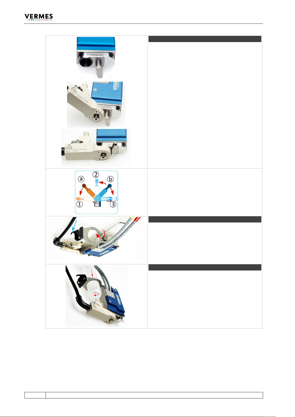
Step 10 (fluid box)
Turn the locking lever by 180° from “Close” to “Open”
position.
Push the fluid box carefully in a 45° angle onto the
valve.
Straighten the fluid box and close the locking lever.
Optional positions
The bayonet fluid box has three different locking
positions (1: 90°, 2: 0°, 3: +90°) in which the valve can
be operated. To fix in locking position 1, mount the
fluid box at position a. To fix in locking position 2 or 3,
mount the fluid box at position b.
Step 11 (cartridge holder)
Screw the cartridge holder on top of the valve body
(torque between 40 – 50 cN.m). Use the MDT 329 or a
hexagon socket key size 2. Depending on the size of
the cartridge, you have to select the correct cartridge
holder. Hook the heater connection of the fluid box
into the cartridge holder (see blue arrow).
Step 12 (cartridge)
Push the cartridge through the cartridge holder and
screw it clockwise into the thread of the cartridge
base.
Tab. 19: Assembling of the valve

Initial Operation
VTK-TR-BA-072e-1 - User Manual MDS 358X Series
49
6.3 Installation of the Microdispensing System
Prior to installation, verify the conditions in the intended location, with respect to the
specification of the system and information detailed in this chapter.
The control unit and the valve have to be installed strictly in conformity with the procedures
described below. The system requires:
• Power supply
• Pneumatic supply
INFORMATION
Read chapter “Safety Notes” first
The entire procedure of installation is reserved to persons reliably informed about the safety
considerations (see chapter 2, page 8).
6.3.1 Installation of the Control Unit
The control unit is designed as a 19” plug-in module, which has to be fixed in the corresponding
rack by means of four pan-head screws at the front side. Leave sufficient space around the unit to
simplify service. Ventilation should be available. Recommended are cases complying with
enclosures according to EN 61010-1 with regard to fire protection.
IMPORTANT NOTE
Potential damage to the control unit
Do not close the four pan-head screws too tight; otherwise the front panel can be damaged (see
torque table Page 19).
To avoid overheating and ensure the required ventilation, a minimum distance between the
control unit and any other object should be maintained (at least 1.5 cm). Heat should neither be
accumulated nor externally be introduced. Do not obstruct natural convection. Ventilation from
the bottom side and air exhaust above is important. Minimum width of ventilation openings is
8 cm x 8 cm.
For high-duty applications (from ca. 300 Hz) or in the case of an air cooled model (AC variants), a
rack with separate ventilation is advisable, since in these situations an airflow of 30 m
3
/h for each
control unit is compulsory.
6.3.2 Installation of the Valve as Part of a Machine
Preferably, mount the valve on an automatic XYZ table or in a similar device (XYZ positioning
system). Stable seat at the fixture of Z-axis is imperative, as the valve should not become loose
during the dispensing process. For this purpose, insert two M4 hex screws to a depth of 4 mm,
through the bores located at the narrow side of the valve. Their distance center to center
amounts to 45 mm. To improve accuracy when positioning the valve on a receptacle,
additionally use the alignment bore and the long hole, located on the narrow side of the valve as
well.