Vermes MDS 358X user Manual.pdf - 第56页
Initial Operation VTK - TR -BA- 072e - 1 - User Manua l MDS 358X S eries 45 Options Reco mmen ded o ption s Differ ent m odels of flu id boxes Differ ent f luid box c onnectors Nozzle heat ing Cleani ng set MDT 301 - Un …
Initial Operation
44
VTK-TR-BA-072e-1 - User Manual MDS 358X Series
6 Initial Operation
6.1 Delivery
VERMES systems are shipped in carefully packed state. Transport damages however can never be
totally excluded, and deadlines stated in insurance contracts should not be exceeded.
6.1.1 Unpacking
After receiving the merchandise:
– Check visually, if any damages can be detected.
If yes:
Detected damages must be notified to the carrier. As soon as the complaint has been confirmed
in writing, contact the responsible forwarder and inform VERMES Microdispensing.
If no damage is detected:
– Open the package.
– Remove any contained subcomponents and parts of the microdispensing system from the
package and check the delivery for completeness.
6.1.2 Content
According to the purchase order, the following components may be included; some of them are
already preassembled:
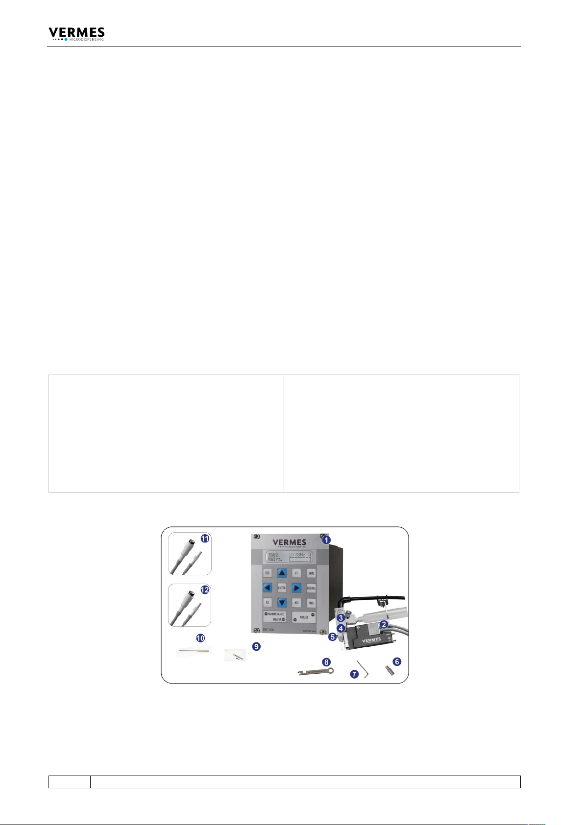
1 Control unit MDC
2 MicroDispensing Valve MDV
3 Fluid box*
4 Nozzle fixation nut*
5 Nozzle insert*
6 MDT 303 - Nozzle Insert
Changing Tool
7 MDT 329 - L-Shape hexagon Key
2 mm
8 MDT 327 – Multi-Function Tool
9 Tappet Grease TF 1 ml syringe
10 MDT 323 - Nozzle Insert –
Squeezing Out Tool TA
11 Actuator cable (red)*
12 Sensor cable (yellow)*
*These parts are included only, if ordered explicitly.
Fig. 20: Content
Initial Operation
VTK-TR-BA-072e-1 - User Manual MDS 358X Series
45
Options Recommended options
Different models of fluid boxes
Different fluid box connectors
Nozzle heating
Cleaning set
MDT 301 - Universal Tool
MDT 306 - Torque Wrench Tool
MDT 324 - Nozzle Insert Cleaning Holder
If the intended application needs particular accessories (e.g. seals made of special material),
consult our Technical Support at once (see Page 7). Do not start the system in incomplete state.
6.2 First Assembling of the Valve
This chapter describes how to ready your microdispensing system for the first dispensing session.
Always make sure all screw couplings sit tight (torque values in paragraph 3.3.11, page 19).
INFORMATION
Some parts preassembled
Some elements of the equipment are usually delivered in preassembled state. In those cases you
can omit the respective steps.
Proceed as follows:
Picture Explanation
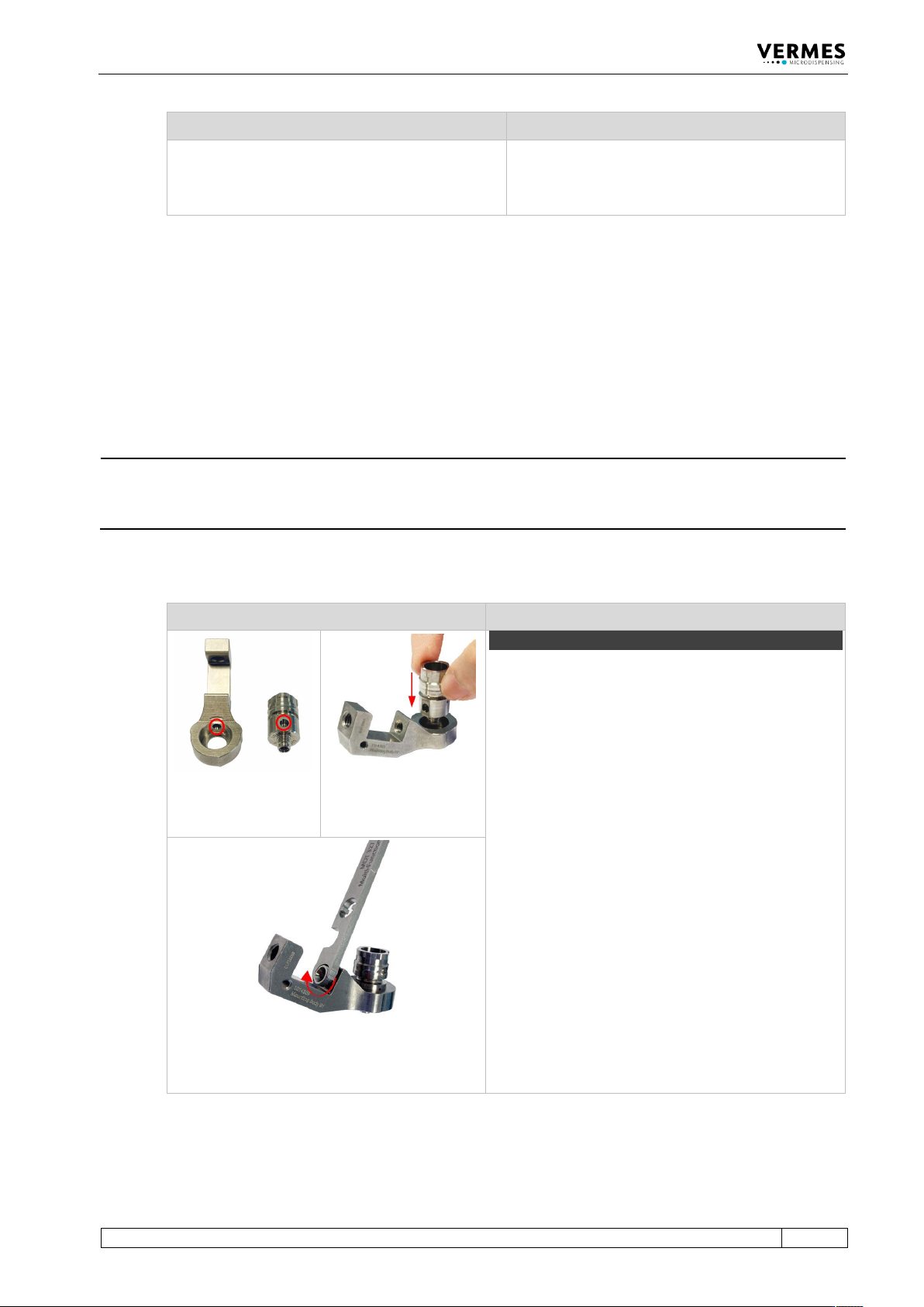
Step 1 (fluid box body)
Information!
This step will be optional, if you re-assemble the valve
later, since usually you would not remove the
Connector BY from the mounting body.
Place the fluid box body on the receptacle of the
mounting body. Align the bore on the fluid box body
with the bore on the mounting body (see circles in
the first picture). The fluid box body will sit in the
mounting body.
Push the Connector BY through the mounting body
into the bore of the fluid box body. Screw the
Connector BY tight (clockwise) by using an MDT 327
(for newer revisions of the Connector BY you can also
use a hexagon key 2.5 or the MDT 306 - Torque
Wrench Tool VM with the Bit Hexagon Key 2.5).
Torques are depending on the material of the
mounting body (stainless steel 90 – 100 cN.m, PEEK 70
– 80 cN.m).
Important Note!
Do not press the fluid box body while fastening the
Connector BY. Otherwise, the Connector BY cannot
correctly grip into the fluid box body.
Initial Operation
46
VTK-TR-BA-072e-1 - User Manual MDS 358X Series
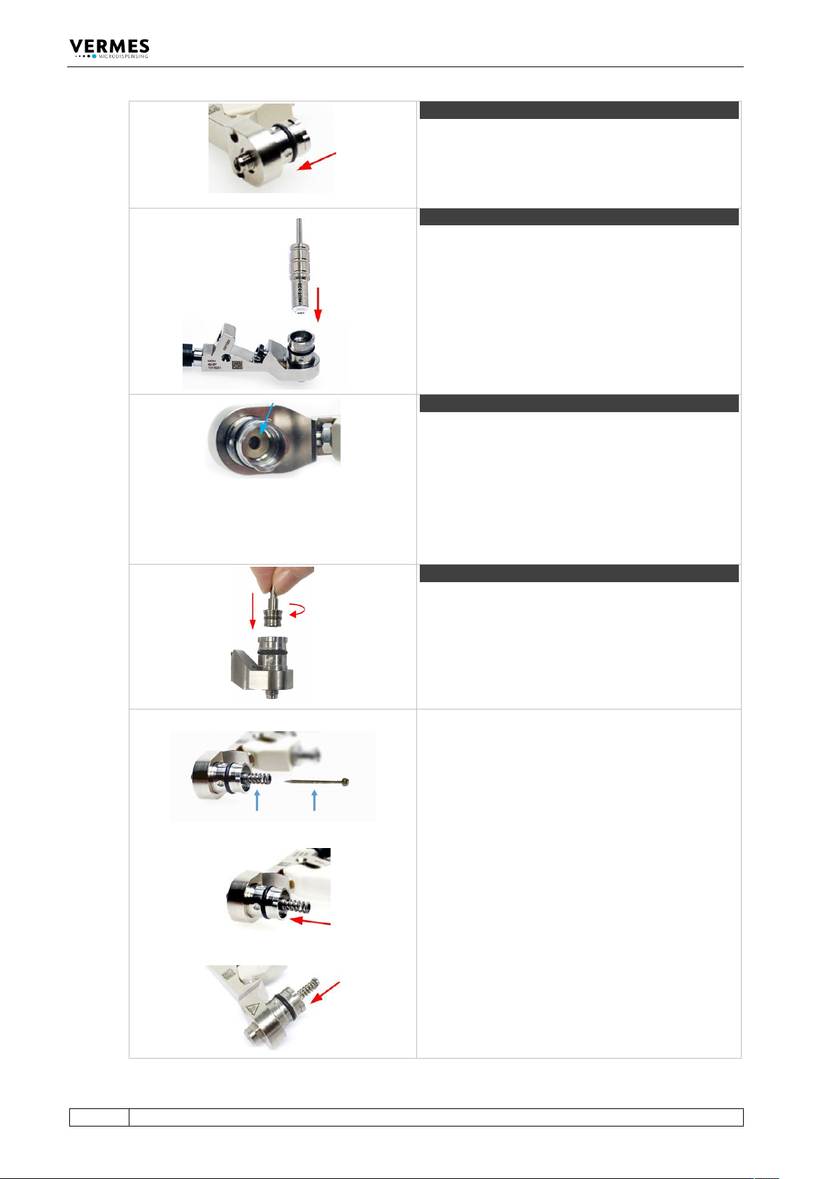
Step 2 (O-ring)
In case that you received the O-ring separately, you
have to mount it onto the fluid box body.
Pull the O-ring over the fluid box body with a pair of
tweezers. Be careful not to damage the O-ring.
Step 3 (tappet sealing)
Use MDT 328 - Tappet Sealing Changing Tool to press
the Tappet Sealing PE/PTFE/HT into the fluid box
body until it sits tight.
Step 4 (tappet centering piece)
Press the tappet centering piece into the fluid box
body. Use the wide end of the MDT 323 - Nozzle Insert
- Squeezing Out Tool TA. Make sure the tappet
centering piece rests flat.
Important note!
You do not need a tappet centering piece, if you use a
2G tappet rod.
Step 5 (tappet and tappet centering screw)
Screw the Tappet Centering Screw BY into the fluid
box. Do not screw it tight yet. Screw it only for two
rotations.
Important note!
Before mounting, please place a small droplet of
Tappet Grease TF (Order no. 1014637; droplet size ca.
2 mm) on the tappet and another on the tappet
spring (for placing see blue arrows in the picture).
Make sure that the tappet tip is free of grease. Rotate
the tappet and pull it in and out for three times to
spread the grease.
Place the tappet spring over the Tappet Centering
Screw BY.
Push the tappet rod through the tappet spring into
the Tappet Centering Screw BY. Make sure the tappet
goes through the tappet sealing.