Vermes MDS 358X user Manual.pdf - 第75页
Operation 64 VTK - TR -BA- 072e - 1 - User Manua l MDS 358X S eries The pa rameter s Rising, Falli ng and Needle L ift use the values pr eset i n the m enu. When the trigger signa l is set to “log ic 1”, the va lve will …

Operation
VTK-TR-BA-072e-1 - User Manual MDS 358X Series
63
7 Operation
7.1 Triggering a Dispense Sequence
There are three different options to trigger a dispense sequence:
• via keypad on the control unit MDC
Press the [trig] button, a dispensing sequence with pre-set parameters will be triggered.
• via RS-232C command
Use the command “VALVE:OPEN” (further commands in paragraph 8.1.2, page 84).
• via PLC signal
Real time triggering by direct I/O (recommended length of signal: between 0.0001 ms and
35 ms; not relevant for Infinite Mode and External Mode)
7.2 Dispensing and Positioning of Dots (Modes)
To combine a multitude of dots to a predefined structure (e.g. a line or a circle), use one of the
following modes:
• Burst Mode
A single trigger impulse by PLC signal causes a predefined number of dispense cycles.
Number of Pulses: predefined value (e.g. 1–32000)
• Single-Shot Mode
Each dispense point is triggered by an individual PLC signal. When dispensing a continuous
feature (such as a straight line or a circle), the frequency of the dispense trigger signal should
be proportional to the trajectory speed of the axis system. This is necessary to achieve a
continuous line width.
Number of Pulses: “1”
• Infinite Mode
– Continuous dispensing as long as the PLC trigger input is “logic 1”. Dispensing will stop when
the signal is changed to “logic 0”
– Number of Pulses:
– “infinite” (when programmed through keypad)
– “0” (when programmed through RS-232C)
The parameters Rising, Falling, Delay, Needle Lift and Open Time use the values preset in the
menu. Is the PLC trigger signal “logic 1”, the MDC sends dispensing impulses, until the signal
changes to “logic 0”.
• Scenario Mode
A complex set of shots is defined via a scenario. This allows the dispensing even of very
complex structures, since up to ten different segments, each with their own set of
parameters, can be combined. Four different scenarios can be saved.
The parameters are set according to the specifications of the scenarios.
• External Mode
The “External Mode” will shift the responsibility of time control of the parameter “Open Time”
to the higher-level machine control. (This may require a very precise time control of the
higher level PLC.) As a result, the valve would function like a “Time-Pressure-Valve”.
Activation of the control unit via RS-232C command by changing the pulse parameters. For
the External Mode set the Open Time to “external”.
Number of Pulses: Should be set to “1” (min delay still applies).
Open Time calculates according to: Length trigger impulse – length Rising = length Open
Time
Operation
64
VTK-TR-BA-072e-1 - User Manual MDS 358X Series
The parameters Rising, Falling and Needle Lift use the values preset in the menu. When the
trigger signal is set to “logic 1”, the valve will open. It will remain open as long as the trigger
signal remains on “logic 1”. It will start to close when the trigger signal is switched to “logic 0”.
After the valve has completely closed, the controller is ready to receive the next trigger signal
to start the process again.
INFORMATION
Open Time and Needle Lift
The maximum value for the “Open Time” is limited to 15 ms, if the “Needle Lift” is set to more
than 80 %. If not, the limit is 3000 ms. The length of the “Open Time” depends on the PLC-signal
(logic 1).
7.3 Parameters for the Dispensing Process
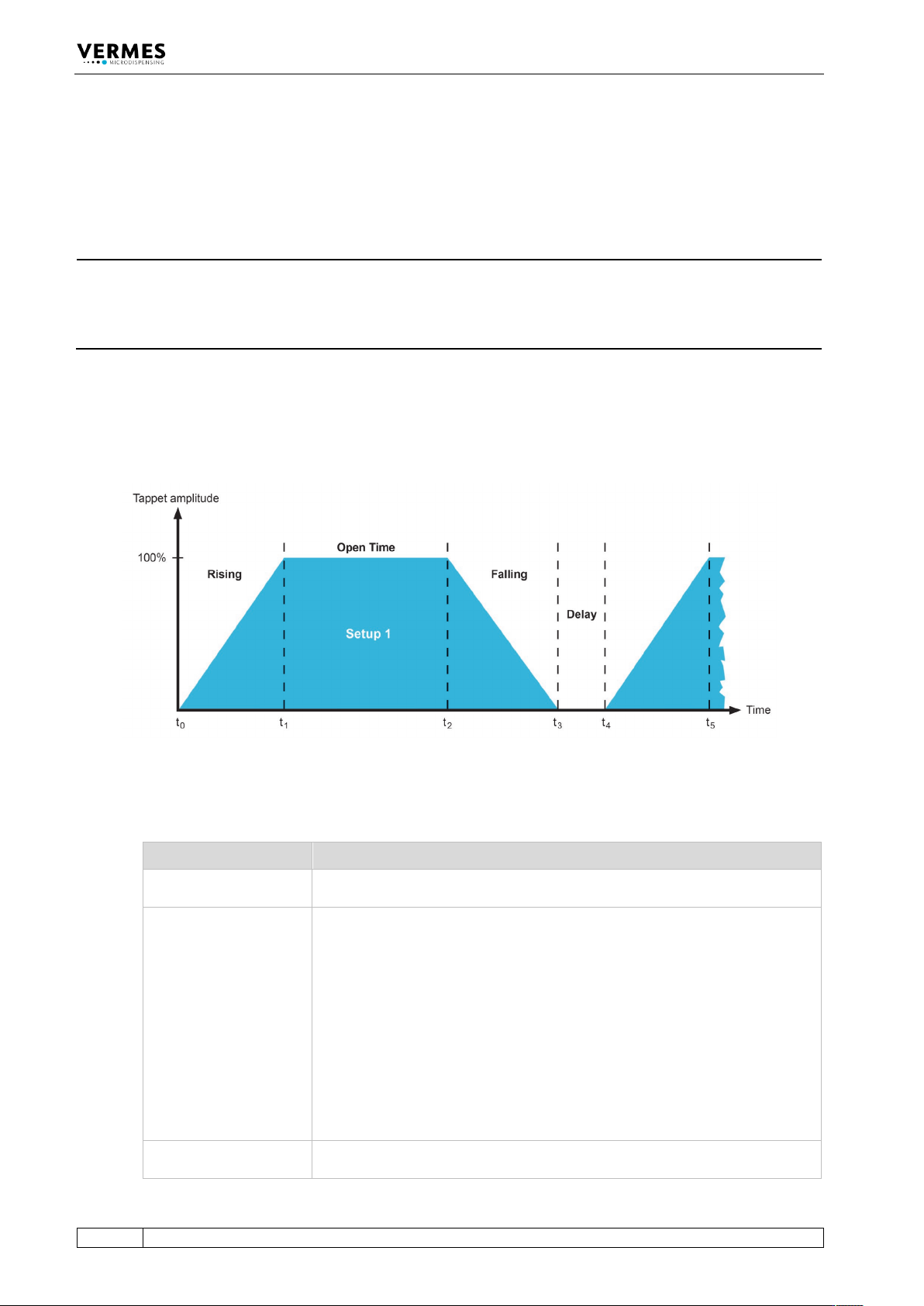
The profile of the system behavior is illustrated below (Y axis = amplitude of the tappet).
Fig. 48: System behavior
This diagram includes the following parameters.
Parameter Description
Rising (RI)
This interval describes the time required until the valve is completely
opened. It is adjustable in steps of 0.01 ms.
Open Time (OT)
During this phase, the valve remains in opened state. It is adjustable in steps
of 0.1 ms.
Max. open time for ≤ 80 % NL = 3000 ms
Max. open time for > 80 % NL = 15 ms
CAUTION!
When working in External mode, the cycle is initiated with following
properties:
For rising, falling, delay and needle lift, the values determined beforehand
are used. Open time however remains active until the signal returns to the
state “logic 0” (for needle lift ≤ 80 %).
Maximum open time for needle lift > 80 % is restricted to 15 ms.
Falling (FA)
The falling ramp of the curve illustrated above represents the time required
for closing the valve. Residual fluid meanwhile is expulsed from the nozzle

Operation
VTK-TR-BA-072e-1 - User Manual MDS 358X Series
65
compression chamber (the cavity at the rear end of the nozzle insert). The
interval is adjustable in steps of 0.01 ms.
Delay (DL)
This waiting phase between two cycles is adjustable in steps of 0.1 ms, but it
is recommended to use at least 0.2 ms.
Needle Lift (NL)
This parameter describes the stroke of the tappet, compared to its full value
of 100 %. For the range between 81 % and 100 %, the valve works in bipolar
mode. The elevated temperature in this range reduces the average frequency
and the lifetime of the valve. A needle lift between 70 % and 80 % is the best
working range.
Tab. 20: Parameters for dispensing