Vermes MDS 358X user Manual.pdf - 第85页
Operation 74 VTK - TR -BA- 072e - 1 - User Manua l MDS 358X S eries ALL” , will also t urn OFF the heat er). You can mov e throu gh the f our opt ions wi th the keys [ ↑ ] and [ ↓ ] . Confirm yo ur choice with [en te r] …

Operation
VTK-TR-BA-072e-1 - User Manual MDS 358X Series
73
7.10 Factory Settings
By recalling the factory settings (implemented by the manufacturer), you return to a predefined
starting position. This is useful to start the input of a new parameter set.
These are the values contained in the factory settings:
RI = 0.50 ms, FA = 0.20 ms, OT = 2.0 ms, NL = 80 %, DL = 10.0 ms and NP = 1.
– Step 1: Press [recall].
– Step 2: [↓] immediately opens this parameter set.
– Step 3: Confirm the selection with [enter].
INFORMATION
Aborting the process
The working configuration (setup 0) is changed to the factory settings. Press [esc] to abort at any
time.
The following table lists the factory settings of the setups.
RI [ms] OT [ms] FA [ms] NL [%] NP DL [ms]
Setup 0
0.50
2.0
0.20
80
1
10.0
Setup 1
1.00
4.0
0.12
80
1
10.0
Setup 2
0.50
2.0
0.20
80
10
10.0
Setup 3
0.40
0.6
0.16
80
1
10.0
Tab. 24: Factory settings of the setups
With Setup ALL (see paragraph 4.5.6 "Submenu “Service-Option”", page 37) Setup 4 – 10 get the
same values as setup 0 (working configuration).
The factory settings for all four scenarios are the same. The PLCStop is “OFF”, the other
parameters are shown in the following table.
Sc.-Segment Setup used ScNP Sc.-Delay
Segment 1
0
as setup NP
10.0 ms
Segment 2
1
as setup NP
10.0 ms
Segment 3
2
as setup NP
10.0 ms
Segment 4
3
as setup NP
10.0 ms
Segment 5
0
as setup NP
10.0 ms
Segment 6
1
as setup NP
10.0 ms
Segment 7
2
as setup NP
10.0 ms
Segment 8
3
as setup NP
10.0 ms
Segment 9
0
as setup NP
10.0 ms
Segment 10
1
as setup NP
10.0 ms
Tab. 25: Factory settings of the scenarios
You can use the menu to reset changed parameters to their factory settings. Go to the submenu
“Service-Option” and press [enter] at “Service Code“. You can enter the four-digit service code
1000. Confirm it with [enter]. Now you can use the keys [←] or [→] to choose between four
options. You can either reset the setups 0 – 3, all setups, all scenarios or every parameter (“Reset

Operation
74
VTK-TR-BA-072e-1 - User Manual MDS 358X Series
ALL”, will also turn OFF the heater). You can move through the four options with the keys [↑] and
[↓]. Confirm your choice with [enter] and confirm the whole process with another [enter].
7.11 Auxiliary Mode
In this mode, you cannot dispense, since there is no internal communication with the valve. The
valve might even be disconnected. But you can use most of the other functions of the MDC, e.g.
check your parameters. While in auxiliary mode, the display shows the message “Auxiliary Mode”
in the bottom line. Auxiliary mode is automatically deactivated when you switch off the MDC.
INFORMATION
Some menu items not shown in auxiliary mode
Some menu items are not shown, while the system is in auxiliary mode (the menu items “Tappet”
and “Nozzle” in the main menu, the submenu “Cooler/Heater”, and the menu items “Reset
Nozzle”, “Reset Tappet”, “Set Nozzle” and “Set Tappet” in the submenu “Status”).
You can enter the auxiliary mode through the menu. You have to enter service code “1000” in the
submenu “Service Code” which is part of the menu “Service Option” (see paragraph 4.5.6,
page 37).
After the error messages 101 (Incorr. Valve) and 199 (Valve Error), you also get the chance to
switch to the auxiliary mode. This allows you to keep control of the information and most of the
functions of the MDC in such a situation (see chapter 11, page 140).
Operation
VTK-TR-BA-072e-1 - User Manual MDS 358X Series
75
7.12 Adjust Offset
If you have a problem with leakage despite a correct adjust (see paragraph 6.5, page 57), you can
use service code 33 to add a little adjust offset. This adjust offset will make sure the valve is
accordingly tighter than indicated by the display value. E.g. with an adjust offset of 4, the adjust
still works between 0 % and 3 %, but the valve is tighter at this value than it would be without
the adjust offset.
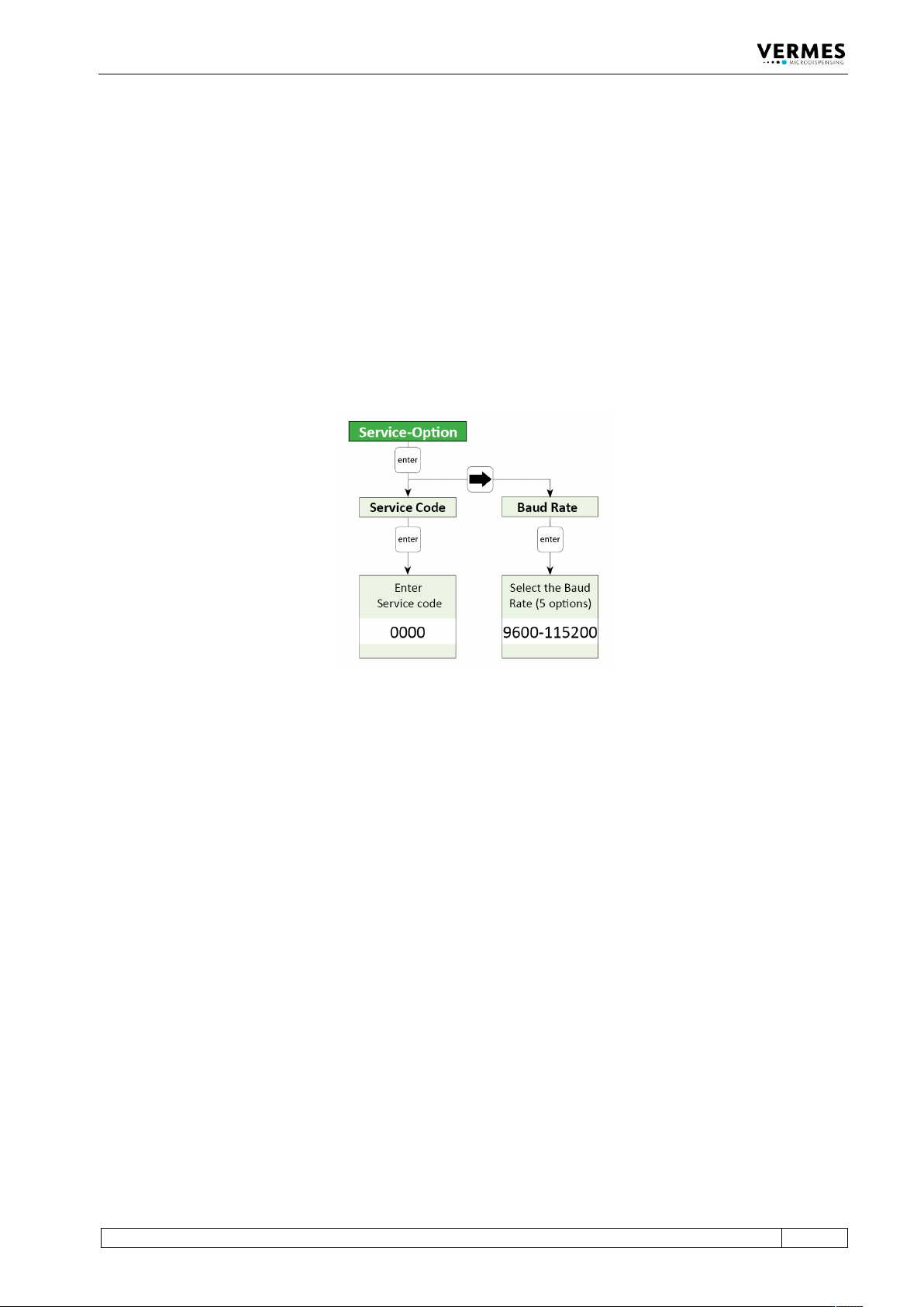
To enter a service code, go to “Main Menu -> Service-Option -> Service Code” (see also the figure
below and paragraph 4.5.6, page 37), press [enter] and enter 33. Once you have confirmed the
service code with [enter], you reach a new submenu called “Adjust Offset”. There you can enter a
value between -5 and 5 (negative means tighter than normal, positive looser than normal).
Confirm your value with [enter]. If you set an adjust offset of 0, the adjust offset is deactivated. It
is advisable to test the system first with an adjust offset value near the default value of 0, e.g. -1
Fig. 55: Submenu Service-Option
Alternatively, you can use the serial command ADJUST:OFFSET:<value>, to set an adjust offset
(see paragraph 8.1.2.2, page 88). The range is the same as if you set it via the keypad. You can also
use the command ADJUST:OFFSET:? to check for an existing adjust offset.
It is important to know that this adjust offset value is only saved in the valve. You have to enter it
again, if you change the valve. But as long as you use the same valve, you can switch off the
control unit and the adjust offset value is kept.