Vermes MDS 358X user Manual.pdf - 第66页
Initial Operation VTK - TR -BA- 072e - 1 - User Manua l MDS 358X S eries 55 Fig. 32 : Connecti on Cable for F CV - AC/HF M12 to MD C Wit h the con nection ca ble, you ca n conn ect the c ooler connect or of the FCV - AC …
Initial Operation
54
VTK-TR-BA-072e-1 - User Manual MDS 358X Series
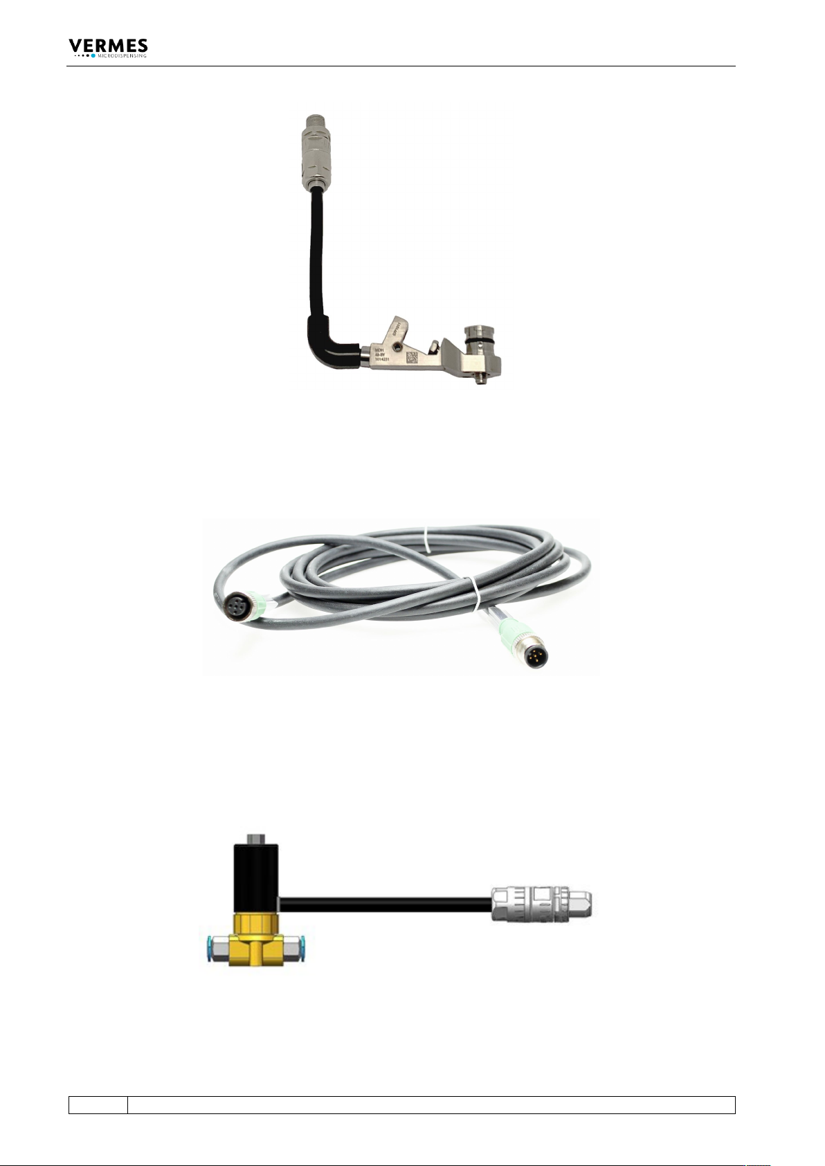
Fig. 29: Heater MDH-48-BY
The Heater Cable 48 V is available in different length (e.g. 2 m, order no. 1014064, see Fig. 30). To
connect the connector of the heater to the rear side of the control unit (“Heater”), use the heater
cable.
Fig. 30: Heater cable 48 V
6.3.3.5 Connecting a Cooler
As an example. the Flow Control Valve FCV-AC 6.0 M12 (order no. 1016265, see Fig. 31) is shown
to demonstrate the connection of a cooler.
Fig. 31: Flow Control Valve FCV-AC 6.0 M12
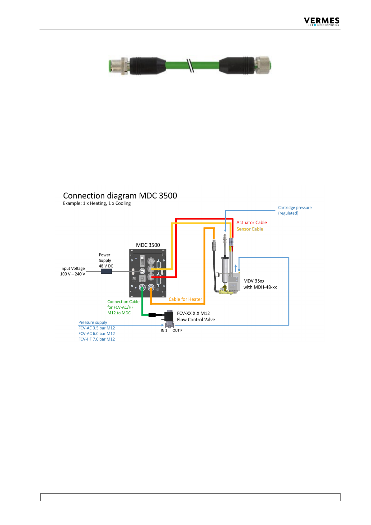
To connect a cooler to the MDC, you need the Connection Cable for FCV-AC/HF M12 to MDC
(length 2 m, order no. 1016252, see Fig. 32, page 55).
Initial Operation
VTK-TR-BA-072e-1 - User Manual MDS 358X Series
55
Fig. 32: Connection Cable for FCV-AC/HF M12 to MDC
With the connection cable, you can connect the cooler connector of the FCV-AC 6.0 M12 to the
rear side of the control unit. Connect the air outlet of the flow control valve to the inlet of the
microdispensing valve (marked with “IN”). Use a suitable hose. Connect the air inlet of the flow
control valve to the compressed air supply.
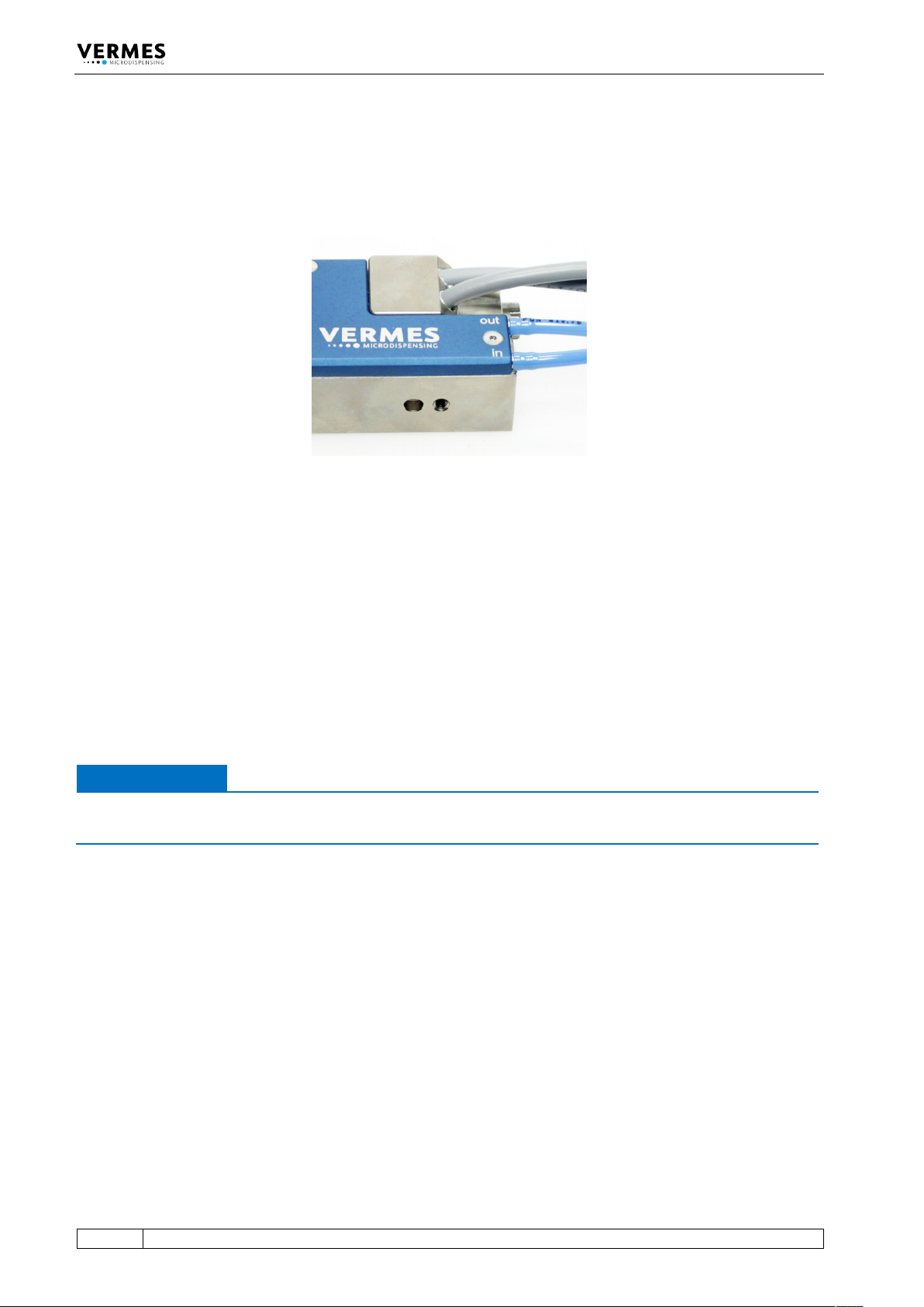
6.3.3.6 Connection Diagram
The picture below offers an overview of how to connection all parts with cables and hoses (using
one flow control valve and one heater as example).
Fig. 33: Connection diagram of MDS 358X
Initial Operation
56
VTK-TR-BA-072e-1 - User Manual MDS 358X Series
6.4 Valves with Air cooling
If you want to air cool your valve with compressed air, you have to connect the air hoses after
finishing the cable connections of the valve. Use 4 mm hoses.
Fig. 34: Valve with air cooling connected
One end of the hose has to be pushed onto the air inlet of the valve (in); the other one is
connected to the air supply.
The second connector (out) represents the outlet, evacuating the heated compressed air from
the valve. You can extend this connection with an air hose. Push one end of the air hose onto the
adapter. When running the hose to the air supply, take care not to impair functions of the system,
or to disturb operators during their work.
For air cooling you should use a compressed-air pressure of about 2 bar. For a hot melt
application or other high temperature applications, you should set the pressure higher, at up to
4 bar.
IMPORTANT NOTE
Quality of compressed air
Quality of compressed air should comply with DIN ISO 8573-1.
The pneumatic supply used for cooling of the valve should be free of fine dust and condensate,
and correspond to classes 1, 4, 2 according to DIN/ISO 8573-1.
• Solid particles: Quality class 1
max. number of particles/m³: 0.1 – 0.5 µm: < 20000, 0.5 – 1 µm: < 400, 1 – 5 µm: < 10
• Water content: Quality class 4
max. pressure dew point +3 °C
• Residual oil: Quality class 2
0.1 mg/m³ max.