Vermes MDS 358X user Manual.pdf - 第95页
Communication Interfaces 84 VTK - TR -BA- 072e - 1 - User Manua l MDS 358X S eries The follow ing paramet er configuration is used for the commu nicatio n with the co ntrol unit : • Synchro nous mode : Half - duplex • Bi…
Communication Interfaces
VTK-TR-BA-072e-1 - User Manual MDS 358X Series
83
8 Communication Interfaces
The control unit has three communication interfaces. There is a 9-pin serial interface, RS-232C, a
15-pin PLC interface and an AUX socket.
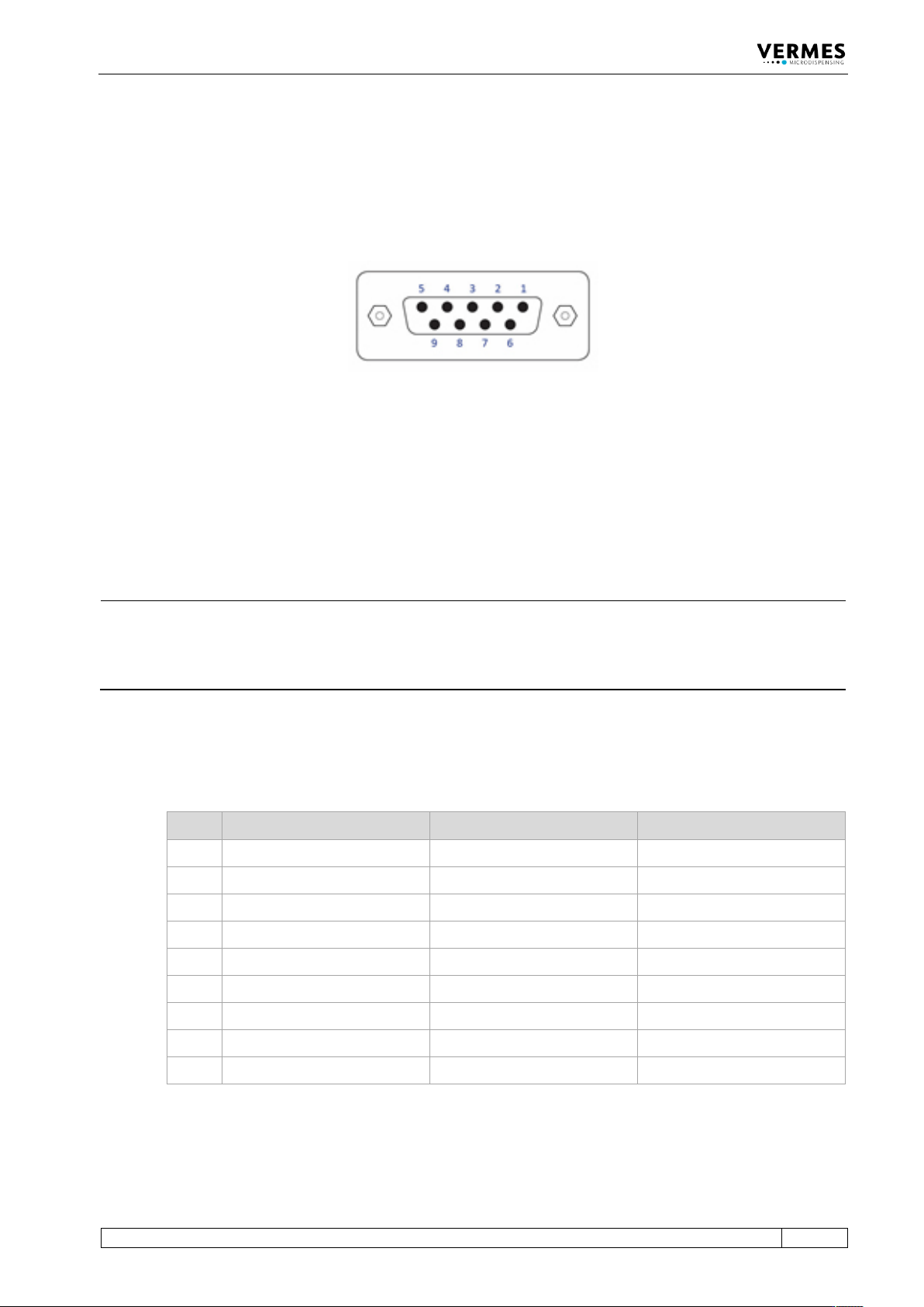
8.1 Serial Interface RS-232C: 9-Pin Sub-D
Fig. 61: Serial interface
The local interface is structured according to SCPI Standard.
These “Standard Commands for Programmable Instruments” represent a standardized set of
instructions used for control and programming, transmitted in form of ASCII text. They can be
generated by any selectable programming language in any environment. The serial interface
operates by means of software handshake. The hardware handshake communications are not in
use.
INFORMATION
Communication while triggering
Do not send instructions through this interface in the course of a running dispensing cycle.
Communication is only possible between distinct sequences (signal DosOK on “high”). This is
especially important during start-up of a heater.
After sending data or parameters to the control unit, you have to wait for the “OK” signal before
you can start further actions. You only can send data while the MDC is in the main menu.
8.1.1 Pin Functions
PIN Characteristics Level Function
1 Reserved ___________ ___________
2
Output
TX
Serial transmission signal
3
Input
RX
Serial reception signal
4
Connected to PIN 6
5
Ground
Ground
6
Connected to PIN 4
7
Reserved
___________
___________
8
Reserved
___________
___________
9
Reserved
___________
___________
The RS-232C log of the control unit uses RS-232C standard and is designed for communication
via a serial cable, connected 1:1, with a Sub-D nine pin connector.

Communication Interfaces
84
VTK-TR-BA-072e-1 - User Manual MDS 358X Series
The following parameter configuration is used for the communication with the control unit:
• Synchronous mode: Half-duplex
• Bits/s: 9600 – 115200 (5 different options available, see paragraph 4.5.6, page 37)
• Start bit: 1
• String length: 8 bit (ASCII)
• Parity: None
• Stop bit: 1
• Log: None
8.1.2 RS-232C Commands
The available commands are listed below. They are explained on the following pages, together
with short examples. This list is according to firmware revision 4085AA1-C.
Each command has to be followed by a line feed (LF, \n, 0x0a) and then a carriage return (CR, \r,
0x0d). It is important to keep to this order!
INFORMATION
Response to commands
The control unit gives a response to every command send to her. Possible answers are:
• A value or set of value, asked for in the command
• OK, to acknowledge a command sent
• NAK (“not acknowledged”), if command sent was incorrect (e.g. incomplete set of values or a
value outside the range, or after start-up a wrong command while the display shows the
message “Please do Adjust”)
• “Auxiliary Mode”, if you send the command “SYSTEM:SHOW:VALVEID” while the system is in
the auxiliary mode.
If there is no response to a command, either the connection is interrupted (e.g. malfunctioning
cable or interface) or the command did not end in a carriage return (0x0d).
The reaction times for the commands are given in the table in the next chapter. The table lists the
values for the highest and lowest baud rate, since these have a great influence on the times. The
length of a response is also influential. There it makes e.g. a big difference with the ESR
commands, if there are only a few errors reported or many of them. Please be aware that your
hardware also influences the reaction times. Therefore, the given times are only guidelines.
Communication Interfaces
VTK-TR-BA-072e-1 - User Manual MDS 358X Series
85
8.1.2.1 Overview
0
RS-232C commands Reaction time (ms)
For baud rate:
9600 bits/s 115200 bits/s
1. *ESR? (e.g. 50 errors)
1280
640
2. *ESR2? (e.g. 50 errors)
2190
640
3. *IDN?
380
340
4. *OPC?
80
70
5. ADJUST:START
160
120
6. ADJUST:OFFSET:?
90
70
7. ADJUST:OFFSET:<offset value>
90
70
8. ADJUST:CALIBRATION:?
120
100
9. ADJUST: CALIBRATION:ON
140
120
10. HEATER:?
340
110
11. HEATER:ID?
90
70
12. HEATER:OFF
110
100
13. HEATER:ON
80
70
14. HEATER:TEMP:<target temperature>
100
90
15. HEATER:LIMITS:<min>,<max>
150
130
16. COOLER:?
80
70
17. COOLER:ID?
90
70
18. COOLER:OFF
100
90
19. COOLER:ON
80
70
20. COOLER:TEMP:<target temperature>
100
90
21. COOLER:OFFSET:<offset>
100
80
22. KEY:ENTER
80
70
23. KEY:ESCAPE
80
70
24. HELP
1880
640
25. LCD?
380
350
26. MAINT:STATUS
690
340
27. MAINT:MESSAGE:OFF
100
90
28. MAINT:MESSAGE:ON
100
80
29. SYSTEM:KLOCK:OFF
90
70
30. SYSTEM:KLOCK:ON
90
70
31. SYSTEM:SHOW:CYCLES
90
70
32. SYSTEM:SHOW:VALVEID
90
70
33. SYSTEM:SHOW:CONTROLLERID
100
70
34. SYSTEM:SHOW:STATUS
690
340