Vermes MDS 358X user Manual.pdf - 第65页
Initial Operation 54 VTK - TR -BA- 072e - 1 - User Manua l MDS 358X S eries Fig. 29 : Heater MDH - 48 -BY The Hea ter Cable 48 V is availab le in di fferent length (e. g. 2 m, order n o. 1014064, see Fig. 30 ). To connec…
Initial Operation
VTK-TR-BA-072e-1 - User Manual MDS 358X Series
53
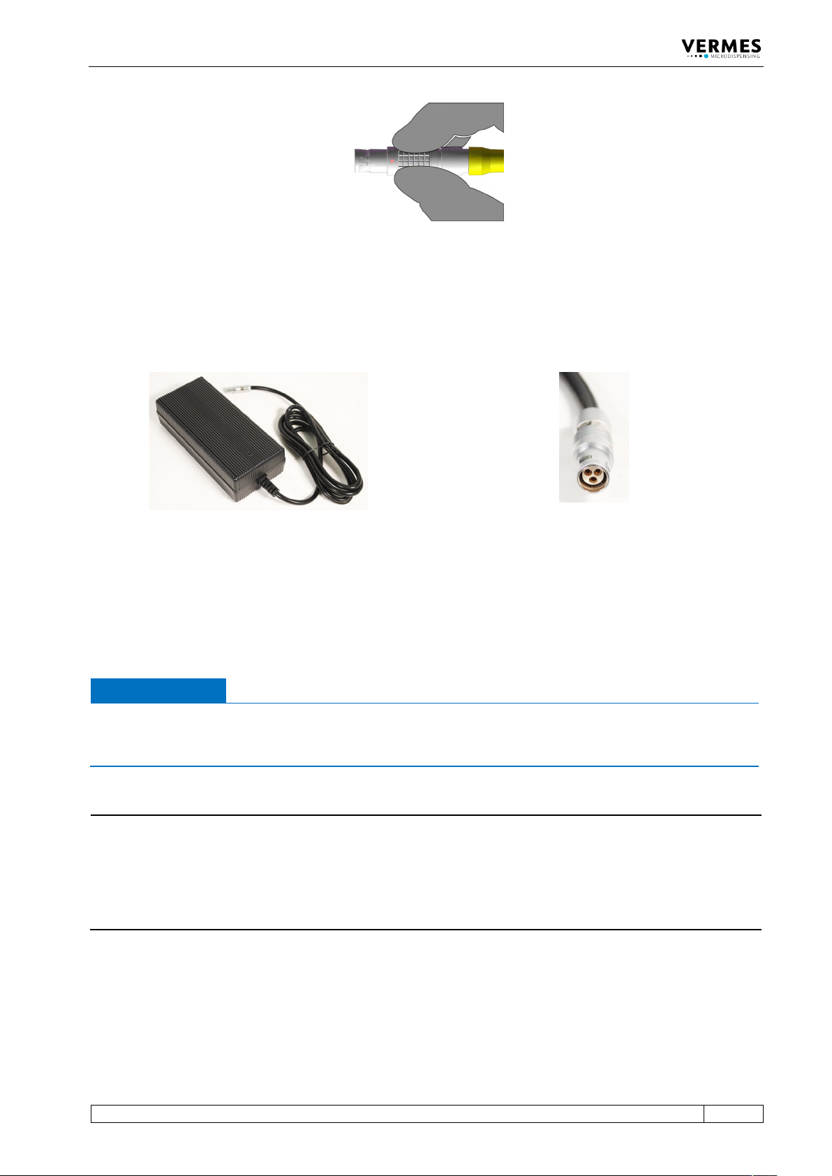
Fig. 27: Connector sensor cable - grip
6.3.3.3 Power Supply
Power to the control unit is supplied by the Switching Power Supply 48 V 4 A Push-Pull (order no.
1015251, see picture below).
Fig. 28: Switching Power Supply 48 V 4 A Push-Pull and its connector
– Step 1: Plug the Push-Pull connector into the socket at the bottom of the rear side of the
control unit. You can find the figure of the rear side in paragraph 4.3, page 23.
– Step 2: Connect the Switching Power Supply to the power supply.
– Step 3: Switch on the control unit by pressing the ON/OFF button on the rear side of the
control unit to the position “ON”.
IMPORTANT NOTE
Valve not connected
If a valve is not connected when switch on the MDC, an error message (“101 wrong valve“)
appears on the screen.
INFORMATION
MDC detects the heater and the cooler during start-up
During start-up, the MDC also checks if a heater and/or a flow control valve is connected. The
messages “Heater connected!” (or “Heater is disconnected!”) and “Cooler connected!” (or “Cooler
is disconnected!”) will be displayed. If the setting is selected, that a heater is automatically
activated during start-up, you need to confirm it by pressing the [enter]-key, when a heater is
connected.
6.3.3.4 Connecting a Heater
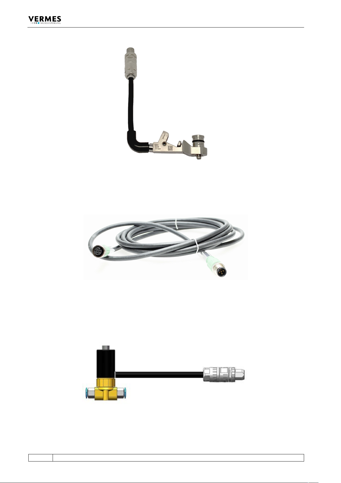
As an example. the heater MDH-48-BY (order no. 1014231, see Fig. 29, page 54) is shown to
demonstrate the connection of a heater.
Initial Operation
54
VTK-TR-BA-072e-1 - User Manual MDS 358X Series
Fig. 29: Heater MDH-48-BY
The Heater Cable 48 V is available in different length (e.g. 2 m, order no. 1014064, see Fig. 30). To
connect the connector of the heater to the rear side of the control unit (“Heater”), use the heater
cable.
Fig. 30: Heater cable 48 V
6.3.3.5 Connecting a Cooler
As an example. the Flow Control Valve FCV-AC 6.0 M12 (order no. 1016265, see Fig. 31) is shown
to demonstrate the connection of a cooler.
Fig. 31: Flow Control Valve FCV-AC 6.0 M12
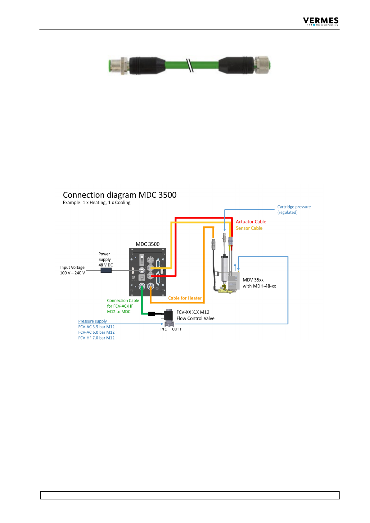
To connect a cooler to the MDC, you need the Connection Cable for FCV-AC/HF M12 to MDC
(length 2 m, order no. 1016252, see Fig. 32, page 55).
Initial Operation
VTK-TR-BA-072e-1 - User Manual MDS 358X Series
55
Fig. 32: Connection Cable for FCV-AC/HF M12 to MDC
With the connection cable, you can connect the cooler connector of the FCV-AC 6.0 M12 to the
rear side of the control unit. Connect the air outlet of the flow control valve to the inlet of the
microdispensing valve (marked with “IN”). Use a suitable hose. Connect the air inlet of the flow
control valve to the compressed air supply.
6.3.3.6 Connection Diagram
The picture below offers an overview of how to connection all parts with cables and hoses (using
one flow control valve and one heater as example).
Fig. 33: Connection diagram of MDS 358X