Vermes MDS 358X user Manual.pdf - 第44页
Control Unit MDC VTK - TR -BA- 072e - 1 - User Manua l MDS 358X S eries 33 To chec k inf or mation a bout the hea ter (e. g. st a tus, t em peratures ) via RS - 232C int erfac e, send th e command “ HEATER:?” (for d etai…
Control Unit MDC
32
VTK-TR-BA-072e-1 - User Manual MDS 358X Series
CAUTION
D
anger of burns through high temperatures!
The nozzle heater can reach very high temperatures.
• Do not touch this area during operation.
• And afterwards only touch it once it has cooled down.
• If possible, wear heat resistant gloves.
To reach a certain target temperature takes time.
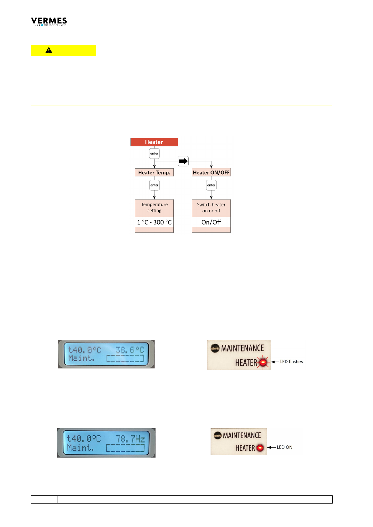
Fig. 11: Submenu “Heater”
All relevant functions of the heater can be set in this submenu. With “Heater Temp.”, you can
select the temperature values with an accuracy of 1 °C. The maximum temperature you can set at
the MDC is 300 °C, but the effective maximum depends on the connected heater (e.g. a
maximum of 180 °C with MDH-48-BY). With “Heater ON/OFF”, you can switch the heater ON and
OFF.
For an example of the display see Fig. 12, when the heater is switched ON, but the target
temperature is not reached yet. The target temperature is shown instead of “Ready” in the upper
left corner of the display. Instead of dispensing frequency, the current temperature is refreshing
in the upper right corner of the display. During this phase, the red Heater LED flashes.
Fig. 12: Before reaching the target temperature
When the target temperature is reached and stable, the dispensing frequency is shown in the
upper right corner of the display (as an example, see Fig. 13). The red Heater LED no longer
flashes, but stays ON.
Fig. 13: The target temperature is reached

Control Unit MDC
34
VTK-TR-BA-072e-1 - User Manual MDS 358X Series
4.5.4 Submenu “Status”
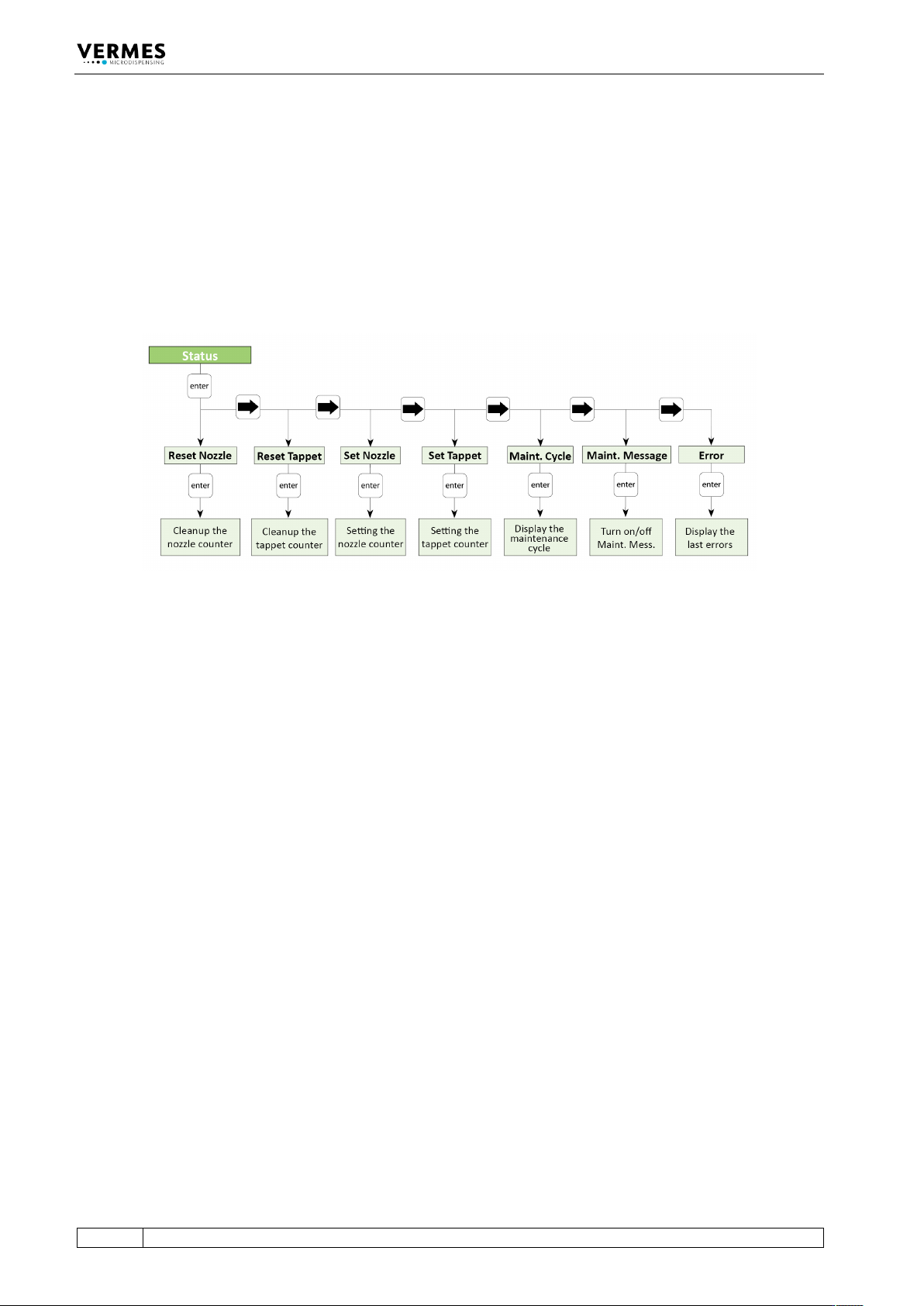
“Maint. Cycle” refers to the unit as a whole and cannot be modified by the user. For the nozzle
and the tappet however, it is possible to determine a fix number of cycles before replacing the
concerning items and to reset the counters after exchange. In “Maint. Message” you can decide
to show or hide the maintenance messages (for more information regarding all aspects
maintenance, see paragraph 10, page 137).
“Error” shows the latest error messages of the system (up to 50), with date and time (UTC). Help
to solve error messages you will find in paragraph 11.2, page 142.
Fig. 14: Submenu “Status”