Vermes MDS 358X user Manual.pdf - 第136页
Cleaning VTK - TR -BA- 072e - 1 - User Manua l MDS 358X S eries 125 – Reinst all the compressed - air con nection as follow s. – Place the PP ad apter fitting on th e cartr idge. Rot ate clockwise, until i t latch es in …
Cleaning
124
VTK-TR-BA-072e-1 - User Manual MDS 358X Series
INFORMATION
Automatic closing
After ca. 2 min the valve closes automatically, in order to protect the actuator.
Alternatively, the procedure can be performed by the RS-232C interface. Use the commands
VALVE:UP and VALVE:DOWN for this purpose.
Step 7:
– Separate the compressed-air connection and remove the cartridge.
Step 8:
– Make sure the collected liquid in the container is disposed of according to local regulation.
9.4.2 Rinsing with a purifying agent
After pre-purification by compressed air, residual liquid may still be present inside the fluid
system (particularly when dispensing high-viscous substances). It can only be removed by a
flushing procedure. For this purpose, the following examples may be suitable agents:
• Distilled water
• Ethanol
• Isopropanol (IPA)
• Acetone
WARNING
Potential chemical reactions
Before the start of the procedure, carefully read the safety data sheet of the dispensed substance.
Ensure compatibility with the cleaning agent.
The cleaning agent itself should not react with any part in contact with the fluid.
Consult the manufacturer in case of need, especially if you intend to use aggressive material.
Step 1:
– Complete the dispensing process. The valve is in closed position. Do NOT switch OFF the
control unit.
Step 2:
– Separate the compressed-air connection.
– The pressure must be reduced to 0 bar.
– Disconnect the PP adapter fitting from the cartridge.
Step 3:
– Replace the used cartridge by a new one.
– The purifying agent can be supplied.
CAUTION
Check for leaks
All of the connectors must be installed and leak-tight.
Step 4:
Cleaning
VTK-TR-BA-072e-1 - User Manual MDS 358X Series
125
– Reinstall the compressed-air connection as follows.
– Place the PP adapter fitting on the cartridge. Rotate clockwise, until it latches in place.
– Connect the PVC hose with the KS4-CK-6 coupler plug to a compressed-air supply. For this
purpose, you require a KD4-1/2-A coupler socket.
– Activate the compressed-air supply.
Step 5:
– Place a container underneath the valve, to collect any liquid dripping out. The container
needs sufficient capacity to contain the purifying agent together with the solved residual
liquid.
Step 6:
– Initiate the purging procedure by pressing [F1].
– Keep the [F1]-key pressed until the procedure is complete and no more liquid flows out
through the nozzle unit.
INFORMATION
Automatic closing
After ca. 2 min the valve closes automatically, in order to protect the actuator.
Alternatively, the procedure can be performed by the RS-232C interface. Use the commands
VALVE:UP and VALVE:DOWN for this purpose.
Step 7:
– Separate the compressed-air connection and remove the cartridge.
Step 8:
– Make sure the collected liquid in the container is disposed of according to local regulation.
Cleaning
126
VTK-TR-BA-072e-1 - User Manual MDS 358X Series
9.4.3 Demount the Valve
CAUTION
No dispensing medium residues
Before demounting the fluid box from the valve, make sure that no dispensing medium is left
inside the system.
Preliminary steps:
– The dispensing process must be completed. The valve is in closed position.
– Deactivate the compressed air supply and remove the Adapter for Compressed Air.
– Switch OFF the control unit and disconnect it from the mains.
– Remove the actuator cable and sensor cable from the valve.
– Detach the valve with fluid box from dispensing robot.
CAUTION
High temperatures, danger of burns
Be careful if you have used a heater with your application. A nozzle heater can reach
temperatures of up to 180 °C. Do not touch this area before it has cooled, since there is the
danger of severe burns. Use heat resistant gloves.
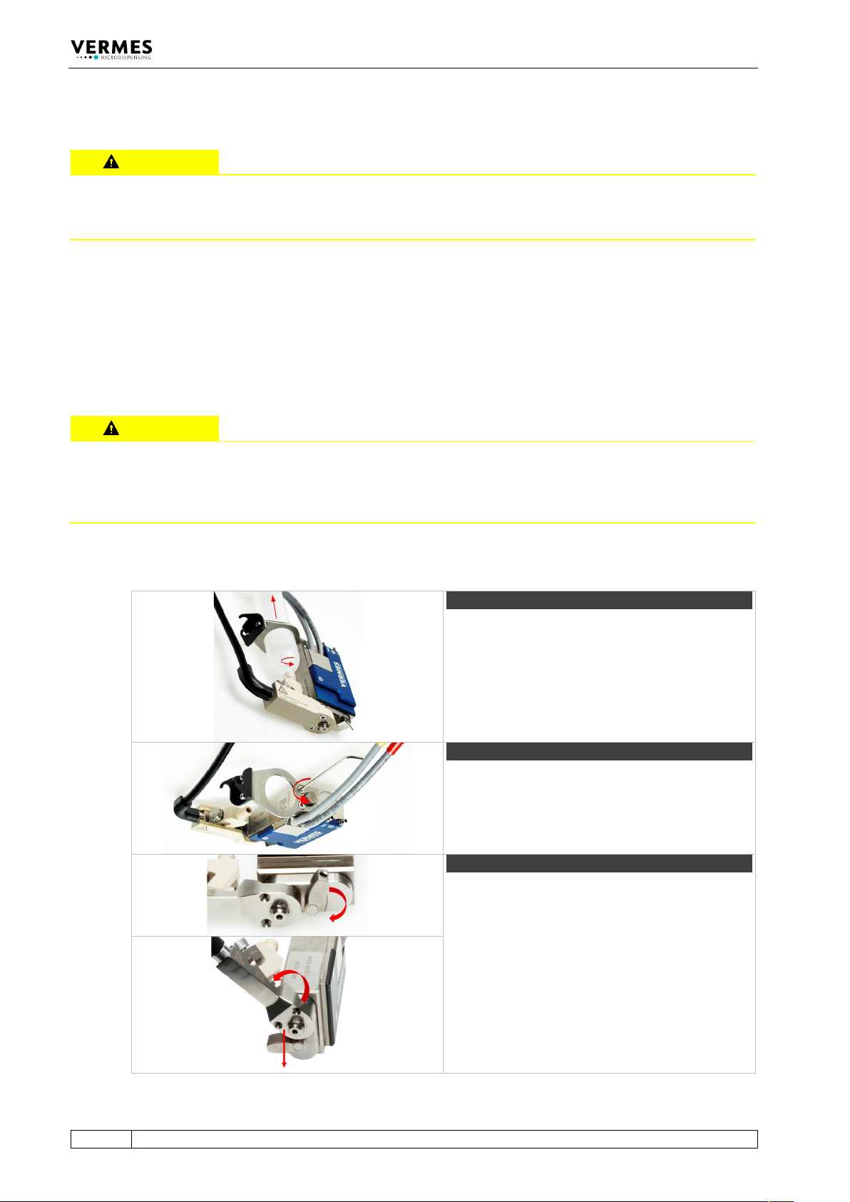
Disassemble the valve as follows.
Step 1 (cartridge)
Unscrew and remove the cartridge. First unscrew
the cartridge counter-clockwise, then pull it out.
Step 2 (cartridge holder)
Screw open the two screws for the cartridge
holder (counter-clockwise). Remove the cartridge
holder.
Step 3 (fluid box)
Turn the locking lever by 180° from “Close” to
“Open”.
Turn the fluid box by 45° and pull it off from the
valve.