Vermes MDS 358X user Manual.pdf - 第147页
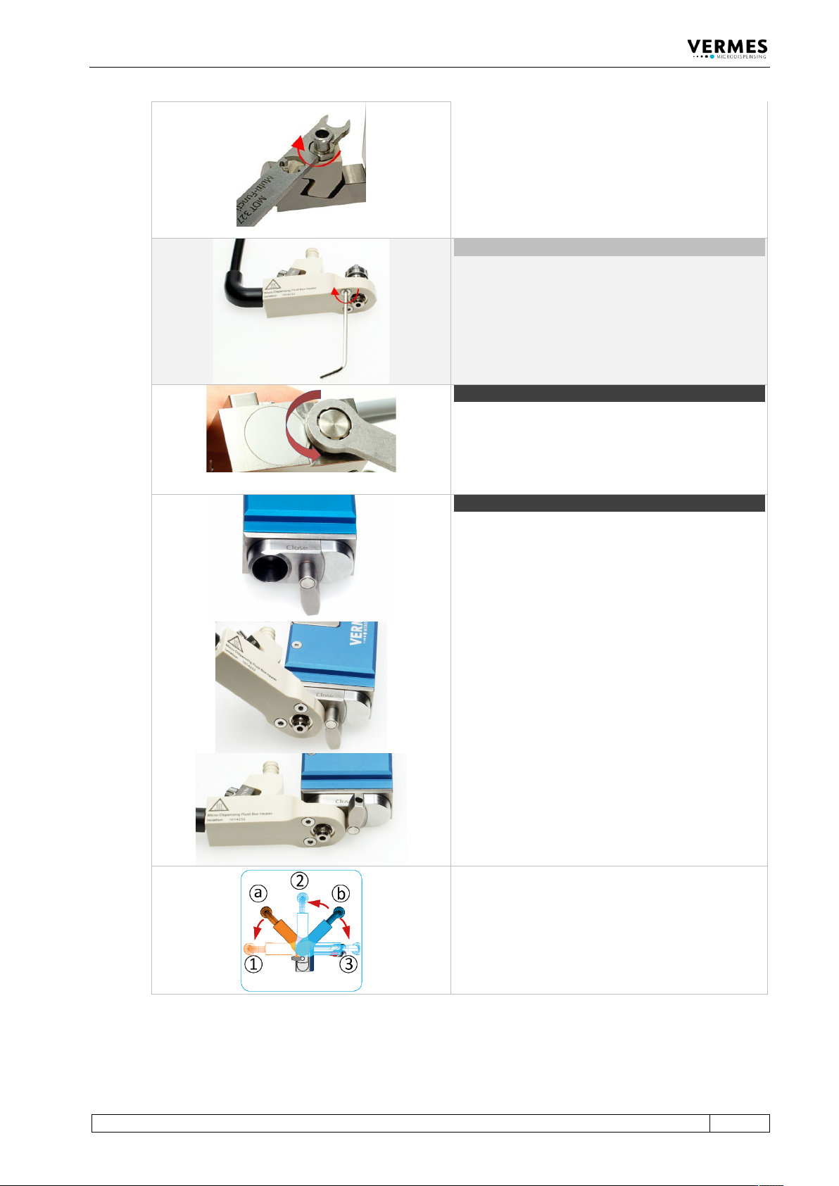
Cleaning 136 VTK - TR -BA- 072e - 1 - User Manua l MDS 358X S eries Step 1 0 (cartridge holder) Screw t he cartridge h older on t op of t he valve b ody (torque b etween 40 – 50 cN. m). Use t he MDT 329 or a hexa gon soc…
Cleaning
VTK-TR-BA-072e-1 - User Manual MDS 358X Series
135
Important note!
In case you use a cartridge base without integrated
luer lock, you need to screw the Fluid Box
Connector Luer Lock into the top bore of the
cartridge base CH. Use the open-ended wrench at
the side of the MDT 327 (hexagon screw size M8,
torque stainless steel 100 – 120 cN.m, PEEK 40 – 60
cN.m).
Optional (isolation body)
For thermally sensitive applications, you might use
an isolation body. Pull it onto the fluid box, until it
clips in. Screw it tight with the two screws for the
isolation body (torque 40 – 50 cN.m). Use the tool
MDT 329.
Step 8 (adjust screw)
Open the adjust screw completely. Screw counter-
clockwise. Use the MDT 327 Multi-Function Tool.
Step 9 (fluid box)
Turn the locking lever by 180° from “Close” to
“Open” position.
Push the fluid box carefully in a 45° angle onto the
valve.
Straighten the fluid box and close the locking lever.
Optional positions
The bayonet fluid box has three different locking
positions (1: -90°, 2: 0°, 3: +90°) in which the valve
can be operated. To fix in locking position 1, mount
the fluid box at position a. To fix in locking position
2 or 3, mount the fluid box at position b.
Cleaning
136
VTK-TR-BA-072e-1 - User Manual MDS 358X Series
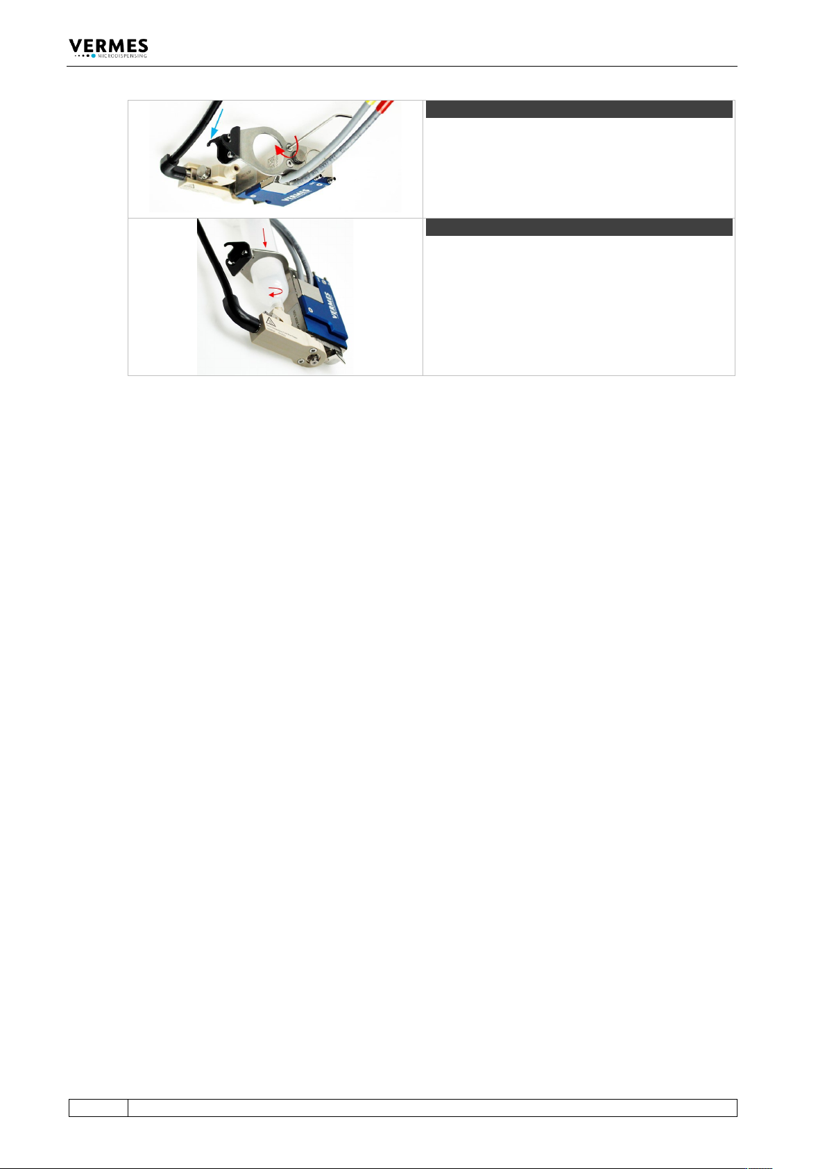
Step 10 (cartridge holder)
Screw the cartridge holder on top of the valve body
(torque between 40 – 50 cN.m). Use the MDT 329 or
a hexagon socket key size 2. Depending on the size
of the cartridge, you have to select the correct
cartridge holder. Hook the heater connection of the
fluid box into the cartridge holder (see blue arrow).
Step 11 (cartridge)
Push the cartridge through the cartridge holder and
screw it clockwise into the thread of the cartridge
base.
Tab. 31: Assembling of the valve
– Finally, connect the actuator and sensor cables as well as the compressed air. You can find
more detailed information in paragraph 6.2, page 45 and paragraph 6.3, page 49.

Maintenance
VTK-TR-BA-072e-1 - User Manual MDS 358X Series
137
10 Maintenance
10.1 Maintenance Indicator
The integrated function “Cycle Count” relates to the valve as a whole and is predetermined by
the manufacturer. As soon as the preset number of cycles is complete (100 %), the red
maintenance LED on the control panel is lit. The manufacturer (or an authorized subcontractor)
has to be informed at once.
In between, you can inspect the current state. Use the function “Maint. Cycle” in the submenu
“Status” (see paragraph 4.5.4, page 34). The result is visualized by eight bars on the screen, each
of them representing 12.5 % of the final value. Be aware that the bar is only updated during a
start-up of the MDC.
INFORMATION
Suppress maintenance messages
Activation of the red maintenance LED can be suppressed by switching “Maint. Message” in the
submenu “Status” to “OFF”. This should only be done, if you know your system very well.
Otherwise, you might cause damages through missed maintenance dates.
Additional cycle numbers can individually be agreed for tappet and nozzle insert. In factory
settings, the value of “Infinite” is assigned to both of the targets. If you wish to check a particular
value, proceed as follows, starting from the first menu level:
• 1x [→]-key = Indicates the interval for exchange of the nozzle insert
• 2x [→]-key = Indicates the interval for exchange of the tappet
To enter a desired final value, you have to use the functions “Set Nozzle” for the nozzle and “Set
Tappet” for the tappet. They are located in the submenu “Status”. Results are also displayed in
the form of 8 bars, each of them representing 12.5 % of the total value. Once 100 % are reached,
the red maintenance LED is lit. The corresponding item (nozzle or tappet) has to be exchanged.
After the exchange, you have to reset the corresponding counter to “0”. Use the functions “Reset
Nozzle” or “Reset Tappet” in submenu “Status” (see paragraph 4.5.4, page 34).