Vermes MDS 358X user Manual.pdf - 第145页
Cleaning 134 VTK - TR -BA- 072e - 1 - User Manua l MDS 358X S eries Step 4 (tappet and tappet centering screw) Screw t he Tappet Centeri ng Screw BY into the flui d box . Do no t screw it ti ght yet. Screw it onl y for t…
Cleaning
VTK-TR-BA-072e-1 - User Manual MDS 358X Series
133
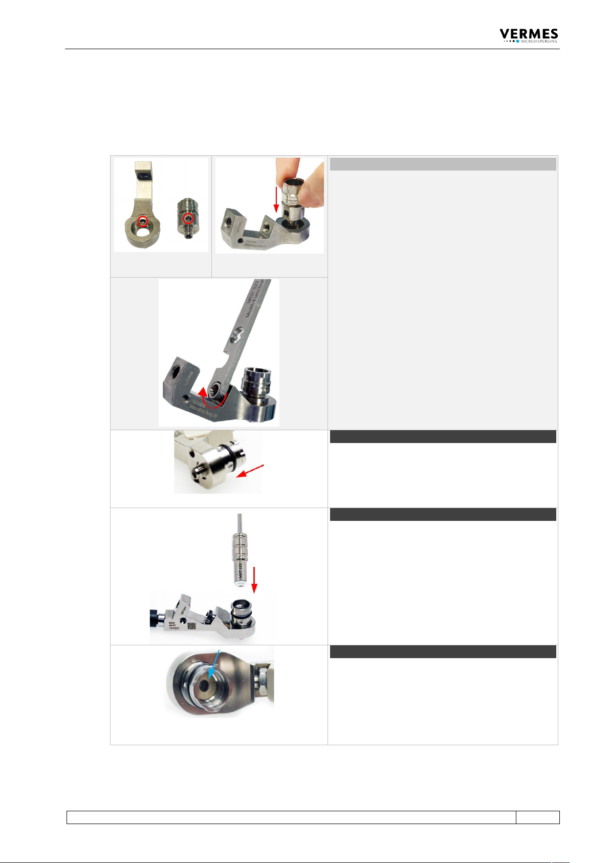
9.4.5 Assembling of the Fluid Box and the Tappet
Re-assemble the valve and its components as follows.
Unusual (connector BY)
In the exceptional case that you removed the
connector BY as well, you have to mount it first.
Place the fluid box body on the receptacle of the
mounting body. Align the bore on the fluid box
body with the bore on the mounting body (see
circles). The fluid box body will fit into the mounting
body, if the mounting direction is correct.
Push the Connector BY through the mounting body
into the bore of the fluid box body. Screw the
Connector BY tight (clockwise) by using an MDT 327
(for newer revisions of the Connector BY you can
also use a hexagon key 2.5 or the Torque Wrench
Tool VM with the Bit Hexagon Key 2.5). Torques are
depending on the material of the mounting body
(stainless steel 90 – 100 cN.m, PEEK 70 – 80 cN.m).
Important Note!
Do not press the fluid box body while fastening the
Connector BY, otherwise, it cannot correctly grip
into the fluid box body.
Step 1 (O-ring)
In case that you removed the O-ring, you have to
mount it onto the fluid box body.
Pull the O-ring over the fluid box body with a pair of
tweezers. Be careful not to damage the O-ring.
Step 2 (tappet sealing)
Use the MDT 328 - Tappet Sealing Changing Tool to
press the Tappet Sealing PE/PTFE/HT into the fluid
box body until it sits tight. When the tappet sealing
sits tight, you will hear a light noise.
Step 3 (tappet centering piece)
Press the tappet centering piece into the fluid box.
Use the MDT 328 to make sure the tappet centering
piece rests flat on the tappet sealing.
Important note!
When using a 2G tappet rod, do not use a tappet
centering piece.
Cleaning
134
VTK-TR-BA-072e-1 - User Manual MDS 358X Series
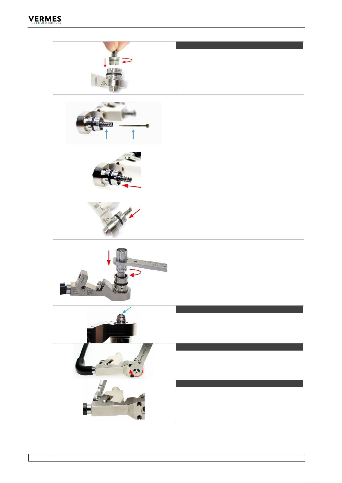
Step 4 (tappet and tappet centering screw)
Screw the Tappet Centering Screw BY into the fluid
box. Do not screw it tight yet. Screw it only for two
rotations.
Important note!
Before mounting, please place a small droplet of
Tappet Grease TF (Order no. 1014637; droplet size
ca. 2 mm) on the tappet and another on the tappet
spring (for placing see blue arrows in the picture).
Make sure that the tappet tip is free of grease.
Rotate the tappet and pull it in and out for three
times to spread the grease.
Place the tappet spring over the Tappet Centering
Screw BY.
Push the tappet rod through the tappet spring into
the Tappet Centering Screw BY. Make sure the
tappet goes through the tappet sealing.
Screw the Tappet Centering Screw BY completely
into the fluid box (torque 100 – 140 cN.m) with MDT
303 - Nozzle Insert Changing Tool.
Make sure the three pins of the MDT 303 fit exactly
into the three holes of the Tappet Centering Screw
BY. Turn the MDT 303 clockwise while pressing it
down slightly to the fluid box.
Combine the MDT 303 with MDT 327 for a better
leverage.
Step 5 (nozzle insert)
Clip the nozzle insert into the fluid box. Use the
small hole of MDT 327 to press the nozzle insert.
Make sure the nozzle insert sits flat.
Step 6 (nozzle fixation nut)
Screw the nozzle fixation nut clockwise onto the
fluid box. Use the MDT 327 - Multi-Function Tool
(torque 150 – 180 cN.m).
Step 7 (cartridge base)
Place the cartridge base onto the fluid box and fix it
with the tightening screw. Screw the tightening
screw clockwise with MDT 327 Multi-Function Tool
(torque 120 – 140 cN.m).
Cleaning
VTK-TR-BA-072e-1 - User Manual MDS 358X Series
135
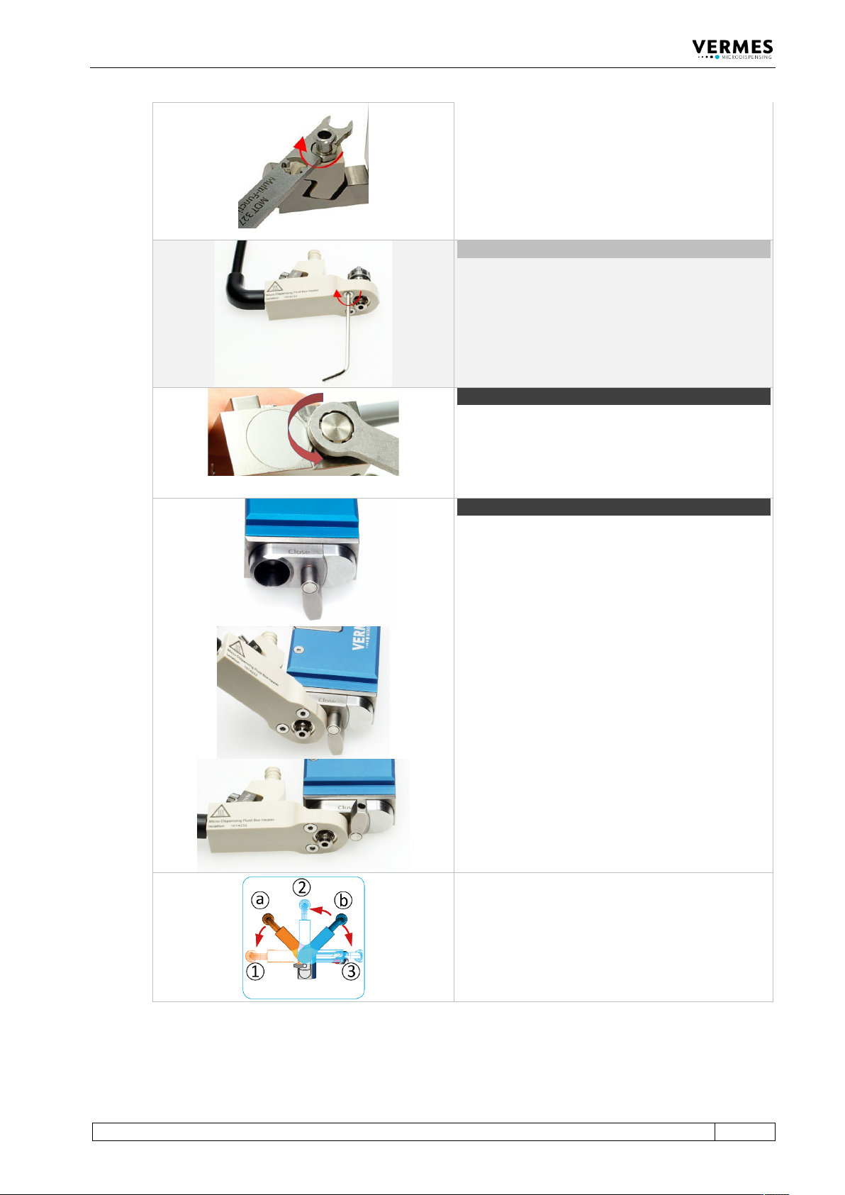
Important note!
In case you use a cartridge base without integrated
luer lock, you need to screw the Fluid Box
Connector Luer Lock into the top bore of the
cartridge base CH. Use the open-ended wrench at
the side of the MDT 327 (hexagon screw size M8,
torque stainless steel 100 – 120 cN.m, PEEK 40 – 60
cN.m).
Optional (isolation body)
For thermally sensitive applications, you might use
an isolation body. Pull it onto the fluid box, until it
clips in. Screw it tight with the two screws for the
isolation body (torque 40 – 50 cN.m). Use the tool
MDT 329.
Step 8 (adjust screw)
Open the adjust screw completely. Screw counter-
clockwise. Use the MDT 327 Multi-Function Tool.
Step 9 (fluid box)
Turn the locking lever by 180° from “Close” to
“Open” position.
Push the fluid box carefully in a 45° angle onto the
valve.
Straighten the fluid box and close the locking lever.
Optional positions
The bayonet fluid box has three different locking
positions (1: -90°, 2: 0°, 3: +90°) in which the valve
can be operated. To fix in locking position 1, mount
the fluid box at position a. To fix in locking position
2 or 3, mount the fluid box at position b.