00197397-02_AI_Stationary_Camera_25_33_X-Serie-S_to_Gxxxx_DE_EN.pdf - 第100页
3 Installation 3.6 Fitting the Reject Bin Sensor 100 Assembly Instructions / Montageanleitung SIPLACE X-Series S Stationary Camera Type 25/33 Stationäre Kamera Typ 25/33 06/2016 Attaching the bracket ► Position the rejec…
3 Installation
3.5 Fitting the Component Reject Bin
Assembly Instructions / Montageanleitung SIPLACE X-Series S Stationary Camera Type 25/33 Stationäre Kamera
Typ 25/33 06/2016
99
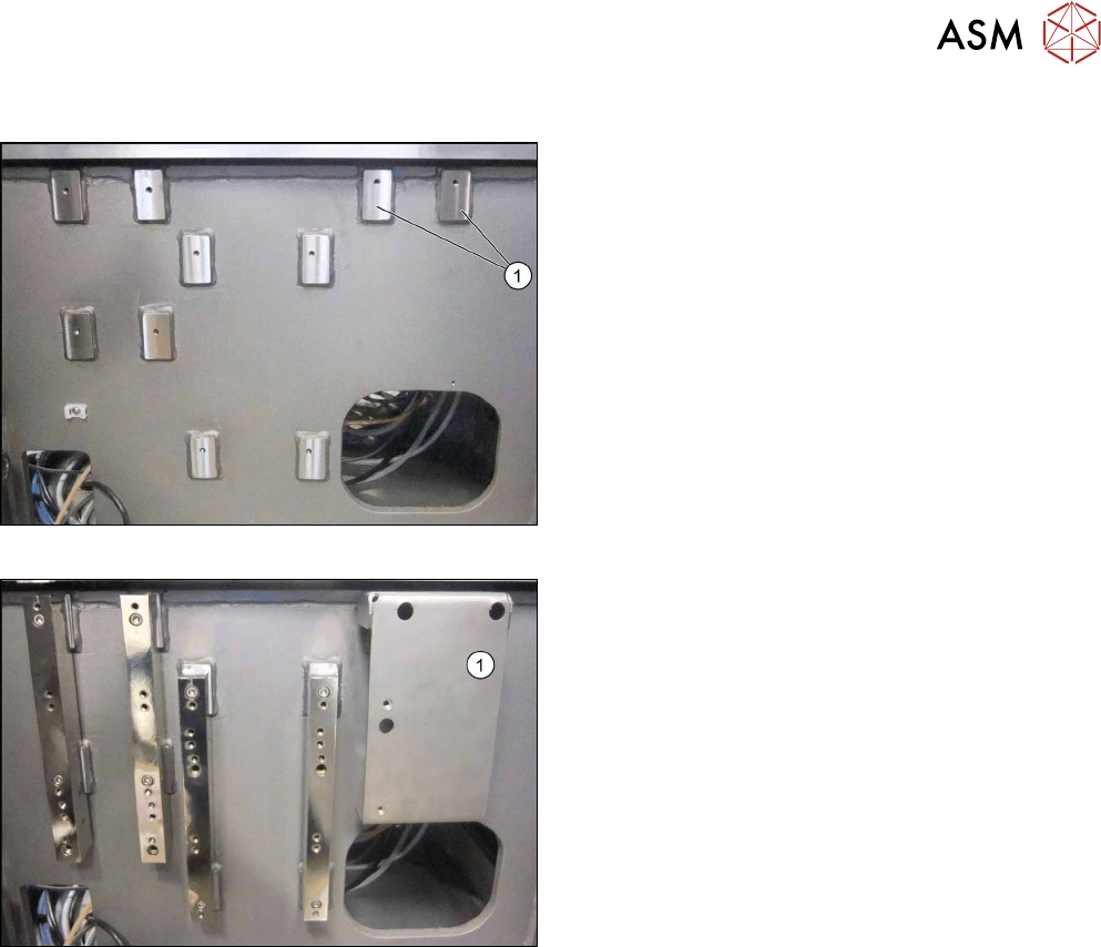
Installation at location 2 and 3
Screw points
► To attach the reject bin, you need to use the
screw fixing points (1) at location 2 and 3 (show-
ing example of location 3 here).
Fixing the retaining plate
► Fix the retaining plate (1) to the screw fixing
points using 2 x M6 x12 screws (03042572-xx).
3 Installation
3.6 Fitting the Reject Bin Sensor
100 Assembly Instructions / Montageanleitung SIPLACE X-Series S Stationary Camera Type 25/33 Stationäre Kamera
Typ 25/33 06/2016
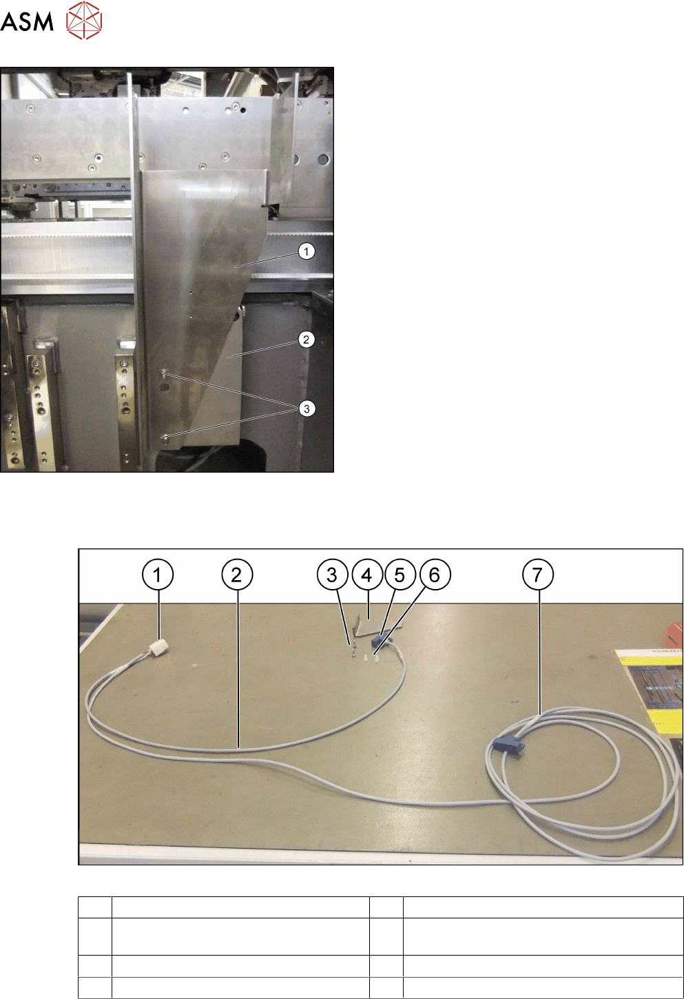
Attaching the bracket
► Position the reject bin bracket (1) on the retaining
plate (2) and fix into place at the drilled holes (3)
using 2 x M6 x12 screws (03042572-xx).
► Continue by fitting the sensor query reject bin
(see 3.6 "Fitting the Reject Bin Sensor" [}100].
3.6 Fitting the Reject Bin Sensor
Fig.10: Reject bin sensor
1 Power connection 2 Short cable end
3 Screws for fastening the retaining
bracket
4 Retaining bracket
5 Sensor "S1" at the short end of the cable 6 Stainless steel screws for fixing the sensor
7 Long end of cable with sensor "S2"
3 Installation
3.6 Fitting the Reject Bin Sensor
Assembly Instructions / Montageanleitung SIPLACE X-Series S Stationary Camera Type 25/33 Stationäre Kamera
Typ 25/33 06/2016
101
Installation
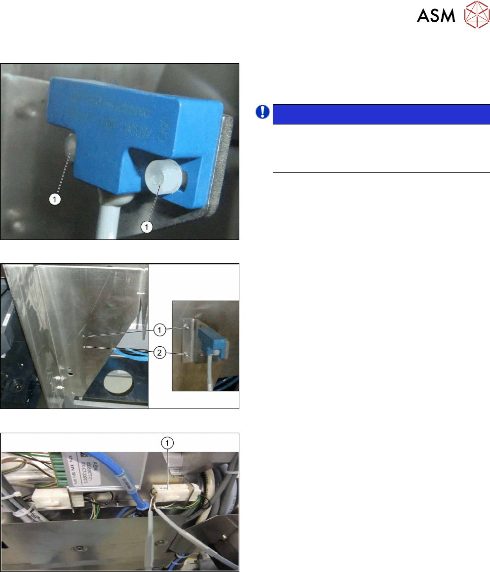
Attaching the sensor
► Fix the sensor to the retaining bracket using two
of the stainless steel screws (1) (shown in the
diagram as plastic screws).
NOTICE!
Use the sensor at the short end of the cable for
all locations without MTC. Use the sensor at the
long end of the cable for location 2 with MTC
(possible for X3 S and X4 S).
.
Fixing the retaining bracket
► Fix the retaining bracket to the reject bin bracket
at the points marked (1) and (2).
Connecting the power
► Connect the power to the COT insert at con-
nector "X2*n" (1).
► When using an X4 S machine with MTC at loca-
tion 2, the long cable from location 3 is run
through the machine base to location 2 and
sensor S2 is fitted to the large reject bin.