00197397-02_AI_Stationary_Camera_25_33_X-Serie-S_to_Gxxxx_DE_EN.pdf - 第82页
3 Installation 3.2 Fitting the Camera 82 Assembly Instructions / Montageanleitung SIPLACE X-Series S Stationary Camera Type 25/33 Stationäre Kamera Typ 25/33 06/2016 3.2.1 Adjusting the Camera Jumper Setting NOTICE Codin…
3 Installation
3.2 Fitting the Camera
Assembly Instructions / Montageanleitung SIPLACE X-Series S Stationary Camera Type 25/33 Stationäre Kamera
Typ 25/33 06/2016
81
3.2 Fitting the Camera
Configurations
IC cameras of type 33 can be installed at all four locations (exception: no installation at PA1 pos-
sible at X4i S).
FC cameras of type 25 can only be installed at locations 2 and 3, only in combination with IC cam-
era type 33.
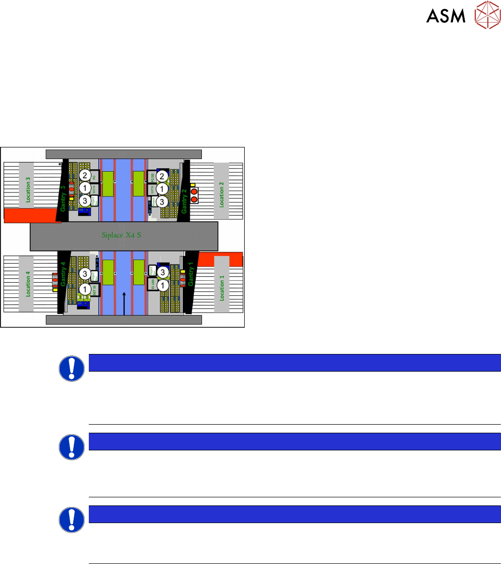
Installation position of cameras (using example of X4 S)
1. IC camera, type 33
2. FC camera / 3D coplan (location2 only)
3. Component reject bin
Location 1 to location 4
NOTICE
TwinHead
The FC camera and the 3D coplan module are only possible together with a TwinHead.
Only one of these options can be fitted at the same location, meaning that either the FC
camera or the 3D coplan module can be used and only in combination with an IC camera.
NOTICE
CPP Head
► A 3D coplan module can be fitted together with an IC camera and a CPP head.
► The combination of an IC camera with a FC camera and a CPP head is not possible.
NOTICE
3D coplan
If a 3D coplanarity is fitted, this only being possible at location 2, the stationary camera (IC
camera) must also be fitted at location 2.
3 Installation
3.2 Fitting the Camera
82 Assembly Instructions / Montageanleitung SIPLACE X-Series S Stationary Camera Type 25/33 Stationäre Kamera
Typ 25/33 06/2016
3.2.1 Adjusting the Camera Jumper Setting
NOTICE
Coding the DIP switch
IC cameras of type 33 up to version 07 are equipped with an 8-pin DIP switch. IC cameras
of type 33 from version 07 are equipped with a 6‑pin DIP switch.
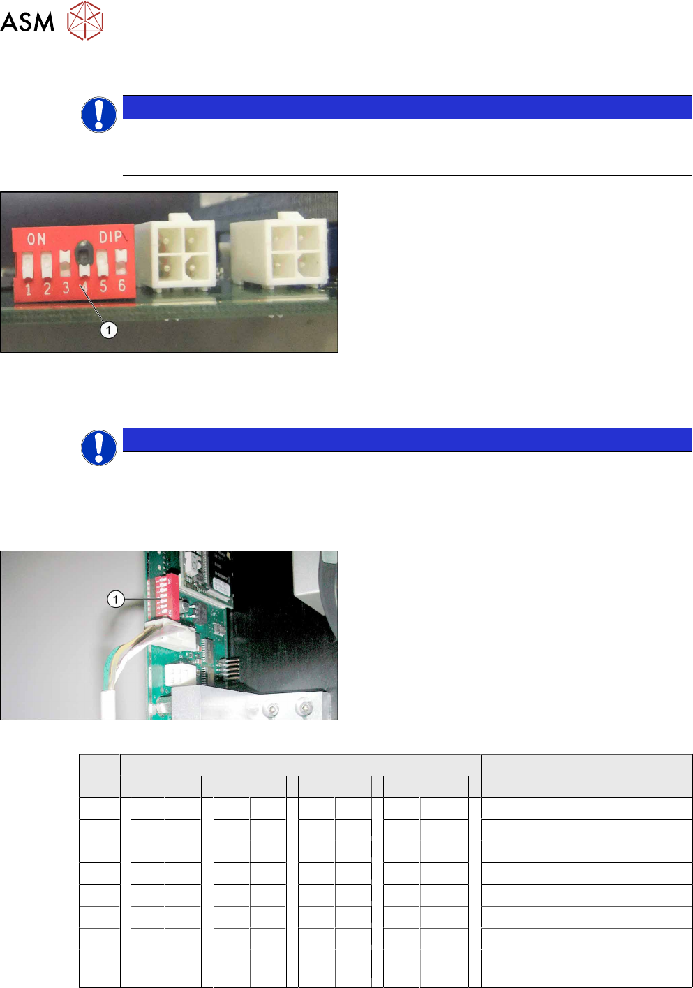
Setting the DIP switch – example of 6-pin switch
shown
► Remove the lighting unit and the cover from the
camera.
► Set the DIP switch (1) at the camera, according
to the configuration and DIP switch type (see
section 3.2.1.2 "Coding the DIP Switch (6
Pin)" [}83]or 3.2.1.1 "Coding the DIP Switch (8
Pin)" [}82]).
► Make a note of the jumper setting on the relevant label on the camera housing.
NOTICE
Exchanging the camera housing when there is more than one camera.
When fitting the cover and the lighting unit, make sure that this is not confused with the one
for a different camera.
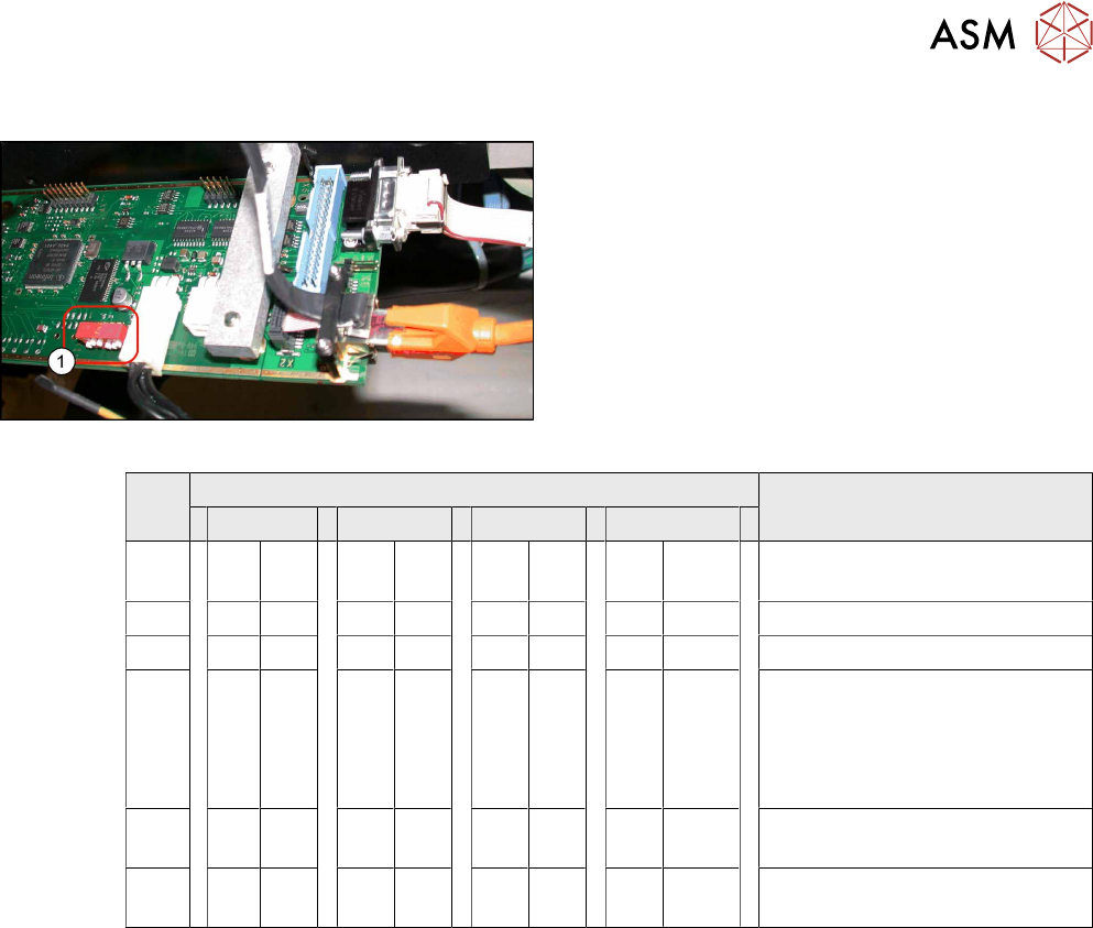
3.2.1.1 Coding the DIP Switch (8 Pin)
Setting the DIP Switches
► Set the DIP switch (1) on the camera.
S Setting for gantry* Comments
1 2 3 4
1 OFF OFF OFF OFF Boot
2 OFF OFF OFF OFF Reset
3 OFF ON OFF ON Gantry ID 0
4 OFF OFF ON ON Gantry ID 1
5 OFF OFF OFF OFF Test
6 OFF OFF OFF OFF CAN terminator
7 ON ON ON ON 1 Mbit/s
8 x X X X X X X x x = OFF: FC camera (type 25)
x = ON: IC camera (type 33/36)
* Not all gantries may be available, depending on the machine type.
3 Installation
3.2 Fitting the Camera
Assembly Instructions / Montageanleitung SIPLACE X-Series S Stationary Camera Type 25/33 Stationäre Kamera
Typ 25/33 06/2016
83
3.2.1.2 Coding the DIP Switch (6 Pin)
Setting the DIP Switches
► Set the DIP switch (1) on the camera.
S Setting for gantry* Comments
1 2 3 4
1 OFF OFF OFF OFF Reset – Do not change this set-
ting!
2 OFF ON OFF ON Gantry ID 0
3 OFF OFF ON ON Gantry ID 1
4 OFF OFF OFF OFF OFF = SMD LED
ON = Standard LED
This switch is delivered with a
fixed presetting. Do not change
this setting!
5 OFF OFF OFF OFF CAN terminator - do not change
this setting!
6 x X X X X X X x x = OFF: FC camera (type 25)
x = ON: IC camera (type 33/36)
* Not all gantries may be available, depending on the machine type.
3.2.2 Fitting the IC Camera Type 33
The camera is fixed at two spacer plates, which have already been screwed to the screw fixing
points on the machine base.
The procedure for fitting these spacer plates and for fixing the cameras is in principle the same at
all locations. Any differences are indicated in the following section.
► Before installation, make sure that the jumper setting for the camera to be fitted is correct (see
3.2.1 "Adjusting the Camera Jumper Setting" [}82]).
See also
2 3.2.3.1 "Fitting the Spacer Plates" [}88]
2 3.2.2.2 "IC Camera Type 33: Fixing the Camera Module" [}87]