00197397-02_AI_Stationary_Camera_25_33_X-Serie-S_to_Gxxxx_DE_EN.pdf - 第65页
1 Introduction 1.2 Preparatory Work... Assembly Instructions / Montageanleitung SIPLACE X-Series S Stationary Camera Type 25/33 Stationäre Kamera Typ 25/33 06/2016 65 ► Release of stored energy: Energy stored as compress…
1 Introduction
1.2 Preparatory Work...
64 Assembly Instructions / Montageanleitung SIPLACE X-Series S Stationary Camera Type 25/33 Stationäre Kamera
Typ 25/33 06/2016
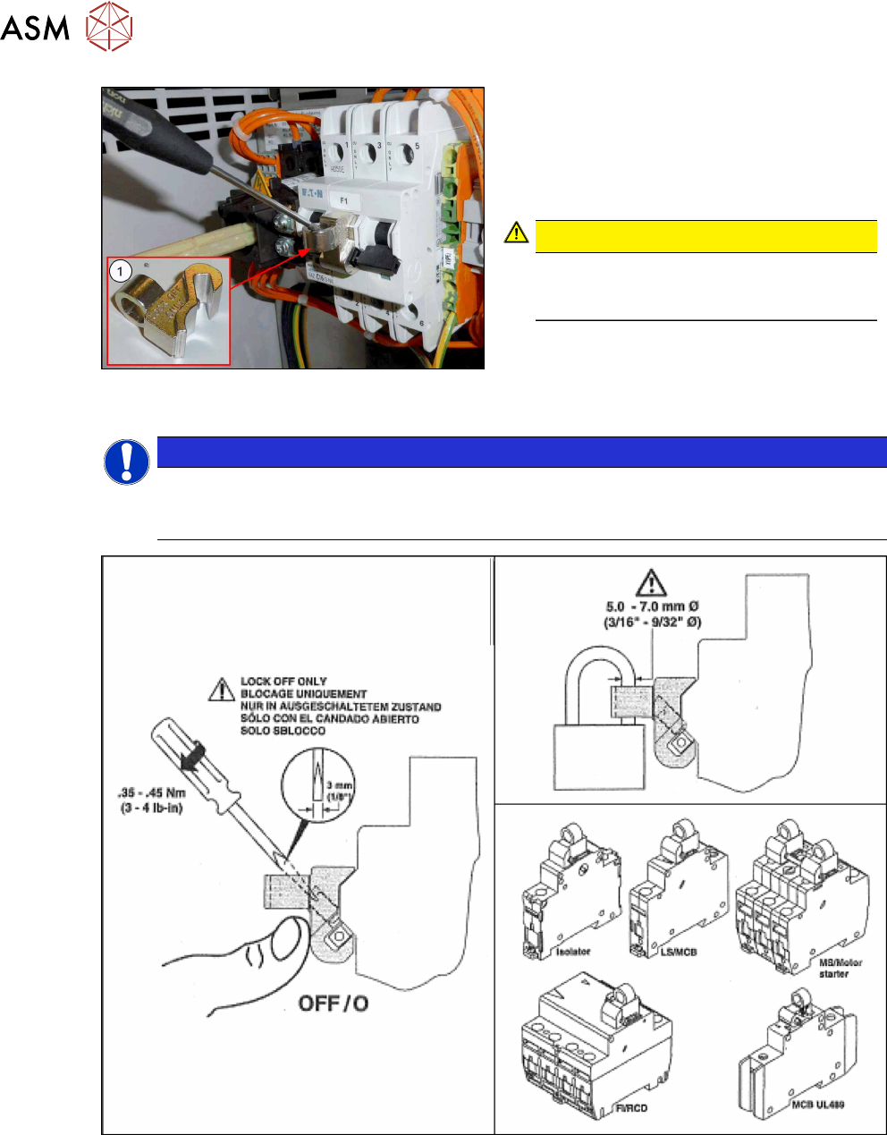
Fig.2: Attaching the lockout attachment Z-IS/SPE-1TE
[03123101-xx]
Secure Circuit Breaker
The lockout attachment can prevent the
machine from being switched on inadvertently.
► Switch off the machine.
► Set the circuit breaker to OFF.
CAUTION!
The lockout attachment may only be at-
tached when the machine is switched
off!
.
► Attach the lockout attachment(1) to the
circuit breaker.
► Secure the circuit breaker with a padlock.
NOTICE
Lockout attachment in the service box of your machine
On machines that are delivered from June 2016, the lockout attachment [03123101‑xx] is
located in the service box.
Fig.3: Lockout attachment Z-IS/SPE-1TE [03123101-xx]
► Alternative: Attaching warning signs:
If a machine can be locked, it must be.
However, there are situations where energy isolating devices cannot accommodate locks. In
these cases, the energy isolating devices must be tagged to warn employees that the
machine is de-energized for servicing. The tag or label must be securely fastened, it must be
placed in a position visible to all and it may only be removed by the person who attached it.

1 Introduction
1.2 Preparatory Work...
Assembly Instructions / Montageanleitung SIPLACE X-Series S Stationary Camera Type 25/33 Stationäre Kamera
Typ 25/33 06/2016
65
► Release of stored energy:
Energy stored as compressed air in the compressed air supply or electrical energy stored in
electrolytic capacitors must be released by appropriate means.
After switching off the machine, wait until the voltages have discharged and the compressed
air has released, so that work can be performed without any risk.
DANGER
Checking for absence of voltage!
► Before you start working, check the power supply for absence of voltage and observe
the waiting times!
► Testing the lock out:
The lock can be easily tested by pressing the START button.
The following steps must be taken to restore the machine to operation.
► Check the workspace. Authorized employees should remove all of their tools and reinstall all
safety features.
► Notify all affected employees.
► Before removing even one lock or tag, inform all workers in the affected area that the machine
is going to be restarted.
► Remove all locks/tags.
Every authorized employee must remove his own lock and shut it away.
► Switch on the machine. Make sure that authorized staff check the equipment in operation to
ensure that all repairs were performed correctly.
Testing
Service personnel may test circuits by energizing them briefly without suspending the Lock Out /
Tag Out Procedure. This may only be done when no other work is being performed by any other
person on the equipment being tested.
It is extremely important that all remote START switches are tagged with the "Do Not Operate" tag
to prevent inadvertent operation of the equipment during these periods.
Responsibilities
●
It shall be the responsibility of the maintenance and service personnel to make sure this pro-
cedure is adhered to.
●
It shall be the responsibility of the maintenance and service personnel's immediate supervisor
to instruct their personnel on this procedure.
●
It shall be the responsibility of the Safety Officer to administer the Lock Out / Tag Out Proced-
ure.
1 Introduction
1.3 Other Instructions
66 Assembly Instructions / Montageanleitung SIPLACE X-Series S Stationary Camera Type 25/33 Stationäre Kamera
Typ 25/33 06/2016
1.3 Other Instructions
1.3.1 Environmentally-Friendly Disposal of Materials and Components
SIPLACE products are manufactured using only materials and parts that can be easily separated
and disposed of in an environmentally-friendly way.
NOTICE
Observe the applicable regulations
The company operating the system has sole responsibility for the proper, environmentally-
friendly disposal of machines, working materials, consumables and wear parts.
► Please observe your national statutory provisions for waste disposal and environ-
mental protection.
1.3.2 Use of Original SIPLACE Accessories and Spare Parts
Only use original spare parts and authorized accessories. The use of other parts will affect safety
and will invalidate the liability for any consequential damage.
1.3.3 ESD Guidelines
1.3.3.1 Definition of ESD
Almost all of the modules in use today are equipped with highly integrated MOS blocks and com-
ponents. The manufacturing techniques used mean that these electronic components are ex-
tremely sensitive to overvoltage and thus to electrostatic discharge.
Fig.4: ESD label
The abbreviation for such modules is "ESD"(Electrostatic Sensitive
Device). This is used internationally, although the German abbreviation
"EGB" may also be seen. The following symbol on cabinet rating plates,
racks or packaging indicates that components which are sensitive to elec-
trostatic discharge have been used and thus that the modules concerned
are also touch-sensitive.
ESDs can be destroyed by voltages and electrostatic charges that are far below the level that can
be perceived by humans. Such voltages occur if a person touches a component or module
without earthing themselves. Components that are exposed to such overvoltage do not generally
appear to be defective immediately - incorrect behavior starts after the component or module has
been in operation for some time.
1.3.3.2 Important Measures to Protect Against Static Charging
► Most plastics can easily become charged and must therefore be kept away from at-risk com-
ponents.
► Always ensure that people, the workplace and packaging are safely earthed when handling
electrostatic sensitive components.