00197397-02_AI_Stationary_Camera_25_33_X-Serie-S_to_Gxxxx_DE_EN.pdf - 第79页
3 Installation 3.1 Performing Preparatory Work Assembly Instructions / Montageanleitung SIPLACE X-Series S Stationary Camera Type 25/33 Stationäre Kamera Typ 25/33 06/2016 79 Moving the COT insert (1) and (2) Fastening s…
3 Installation
3.1 Performing Preparatory Work
78 Assembly Instructions / Montageanleitung SIPLACE X-Series S Stationary Camera Type 25/33 Stationäre Kamera
Typ 25/33 06/2016
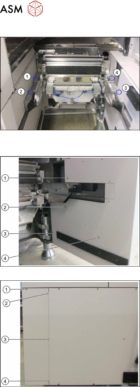
3.1.1.4 Moving the COT Insert Outwards
Location 4 on the X4i S – at first table position
(1) to (4): Positions of screws fastening the COT insert
To gain access to the screw at (3), you need to re-
move the outer side cover.
See also: 4.4.1 "Installation Positions of COT Insert
and Manual Table (Table Positions)" [}107]
Removing the side cover
Location 4 on X4i S – inner side cover
(1) to (3): Positions of fastening screws
► Remove the screws at (1) to (4).
Location 4 on X4i S – outer side cover
(1) to (4): Positions of fastening screws
► Remove the screw at (1).
► Loosen the screws at (2) to (4).
► Remove the side cover.
3 Installation
3.1 Performing Preparatory Work
Assembly Instructions / Montageanleitung SIPLACE X-Series S Stationary Camera Type 25/33 Stationäre Kamera
Typ 25/33 06/2016
79
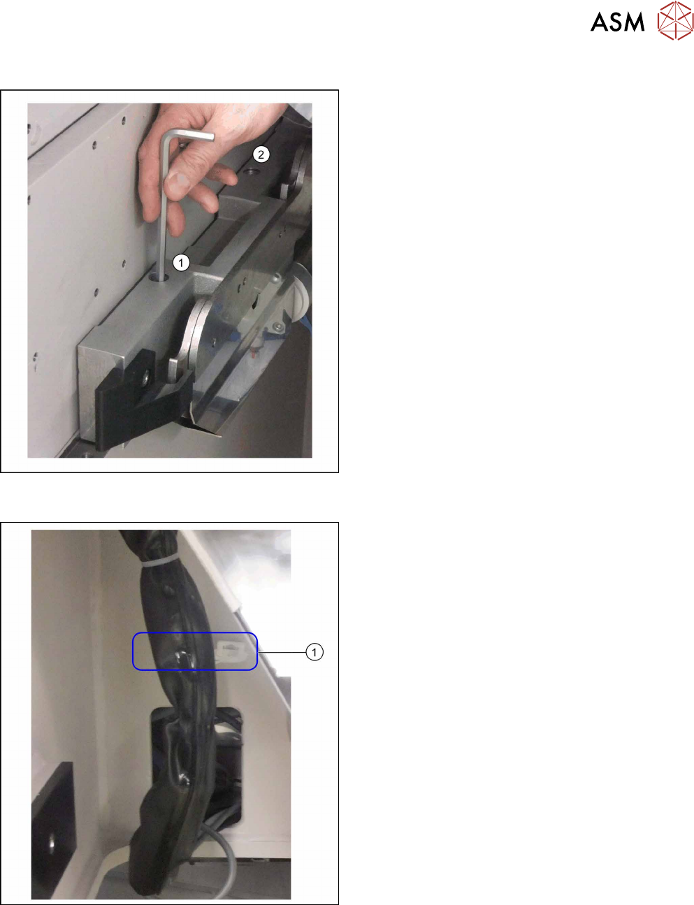
Moving the COT insert
(1) and (2) Fastening screws on the left of the COT in-
sert
► Remove the two fastening screws on both the left
and the right of the COT insert using an Allen key
or a T-handle.
Fixture point on machine frame
► Remove the cable ties at (1).
3 Installation
3.1 Performing Preparatory Work
80 Assembly Instructions / Montageanleitung SIPLACE X-Series S Stationary Camera Type 25/33 Stationäre Kamera
Typ 25/33 06/2016
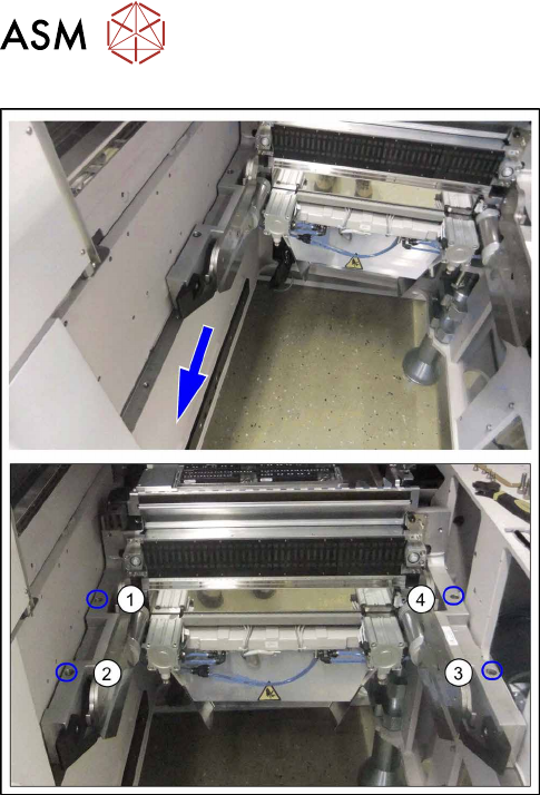
Secure COT insert behind second table position
► Move the COT insert outwards by approx.
125 mm i.e. one hole pattern back.
► Fix the COT insert on each side with two
screws (1) to (4).