00197397-02_AI_Stationary_Camera_25_33_X-Serie-S_to_Gxxxx_DE_EN.pdf - 第72页
2 Brief Description 2.5 Scope of Delivery 72 Assembly Instructions / Montageanleitung SIPLACE X-Series S Stationary Camera Type 25/33 Stationäre Kamera Typ 25/33 06/2016 2.5 Scope of Delivery Component camera, stationary…
2 Brief Description
2.2 Overview of X Series S Machines
Assembly Instructions / Montageanleitung SIPLACE X-Series S Stationary Camera Type 25/33 Stationäre Kamera
Typ 25/33 06/2016
71
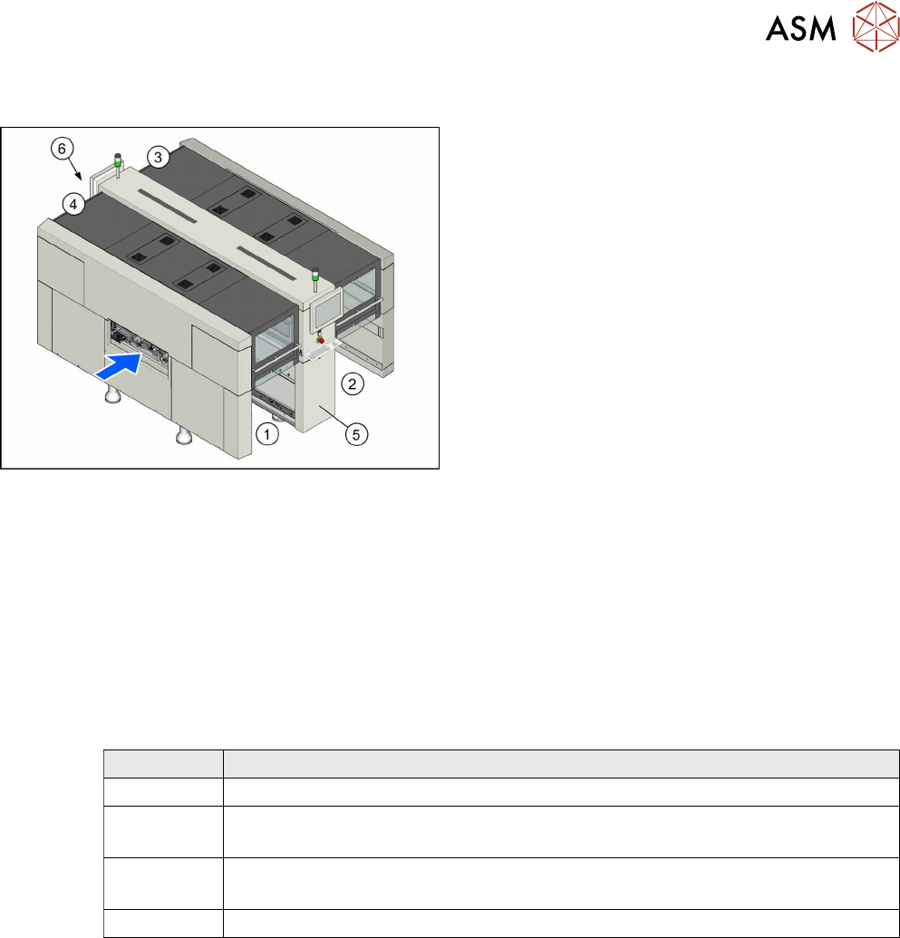
2.2 Overview of X Series S Machines
Machine overview (example of X3 S, X4 S shown)
1. Location 1
2. Location 2
3. Location 3
4. Location 4
5. GCU, BoxPC, I/O modules
6. Power Supply
2.3 Requirements
Machines with only C&P20A heads will only have one hotlink card fitted. When converting to a CPP
or TwinHead, you need to install an additional "hotlink interface PCI-A24-K01" [03052135Sxx] in
the Box PC.
2.4 Configurations
The following stationary camera configurations can be fitted at the locations of X3 S, X4 S and
X4i S machines, with the exception of PA1:
Location Configuration
1 IC camera, type 33
2 IC camera, type 33
IC camera type 33 and FC camera type 25
3 IC camera, type 33
IC camera type 33 and FC camera type 25
4 IC camera, type 33
2 Brief Description
2.5 Scope of Delivery
72 Assembly Instructions / Montageanleitung SIPLACE X-Series S Stationary Camera Type 25/33 Stationäre Kamera
Typ 25/33 06/2016
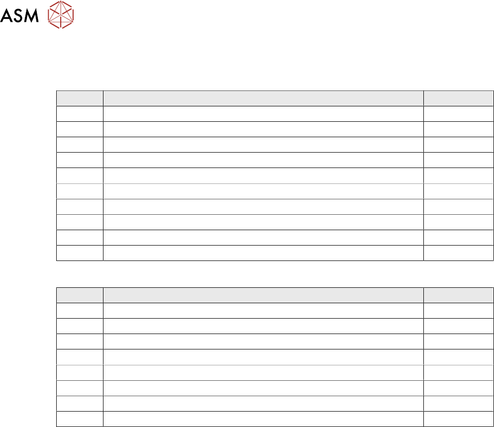
2.5 Scope of Delivery
Component camera, stationary P&P (type 33) 55x45 [00519893Sxx]
Quantity Designation Item No.
1 Component camera, stationary P+P (type 33) 55x45 digital 03016339-xx
1 Assy holder calibr. jig repository LOC4 03098073-xx
1 IC camera adaptor assembly LOC4 SX4a 03099004-xx
1 Waste box TwinHead PA1 SX4a assembly 03097354-xx
1 IC camera adaptor assembly 03099054-xx
1 Connecting sheet assembly 03097430-xx
1 Cable: reject bin sensors 03090846-xx
1 Option parts reject bin 03090847-xx
1 Retaining plate assembly for reject bin assembly 03094709-xx
1 Patch cable Cat6 600MHz 2xRJ45 3m OG 03039067-xx
Stationary P&P component camera, type 25 16 x 16, digital (FC camera) [00519829-xx]
Count Description Item No.
1 Component camera, stationary P+P (type 25) 16x16 digit. 03020578-
1 IC camera adaptor assembly SX4 03080926-
1 Retro. man. Flip-Chip camera 16x16, X-Series 00194554-
2 DIN 913 - M 6 x 50-ST 03005958-
1 Cable: extension camera bus IC/FC camera 03055279-
1 Cable: extension power FC camera 03055298-
1 CAN bus: IC camera 03050239-
1 Support plate FC 03077911-
2.6 Tools and Equipment Required
●
ESD tape
●
Shelf for lighting unit
●
Set of Allen keys
●
Set of screwdrivers
●
Universal pliers
●
Long Allen key with T-handle (at least 30 cm) size 6
●
Cable ties
●
Microfiber cloth for cleaning optical assemblies
●
Assembly Instructions "SIPLACE X-Series S, stationary camera type 25/33" [DE+EN:
00197397-xx]
●
If necessary: Assembly instructions "Row 2 Nozzle Changer – Nozzle Changer Before
MTC" [DE+EN:00197369‑xx]
●
Service manual "SIPLACE X-Series S" [DE: 00197041-xx] [EN: 00197042-xx]
2.7 Required Working Time
The complete installation will take approx. between 1 and 2 hours. The work time depends primar-
ily on the type of machine, the location and the camera configuration at the location.
3 Installation
3.1 Performing Preparatory Work
Assembly Instructions / Montageanleitung SIPLACE X-Series S Stationary Camera Type 25/33 Stationäre Kamera
Typ 25/33 06/2016
73
3 Installation
NOTICE
Assembly Differences
The stationary cameras of type 33 (IC camera) and type 25 (FC camera) can be installed in
all X-Series S machine types. The design and assembly of the individual machine types is
the same in principle. Any relevant differences will be mentioned explicitly.
► Machines up to serial number Gxxxx accommodate stationary cameras with a hotlink
interface (without GigE).
Please read the assembly instructions "SIPLACE X-Series S – Stationary Camera
Type 25/33" [00197397‑xx].
► Machines from serial number Hxxxx accommodate stationary cameras with GigE.
Please read the assembly instructions "SIPLACE X-Series S – Stationary Camera
Type 25/33 (GigE)" [00197710‑xx].
CAUTION
Do not hold or carry the camera by its electronics unit.
The camera electronics assembly is a sensitive unit and can be easily damaged.
► Only hold or carry the camera by its metal frame.
► Always pull the illumination unit carefully up and off.
► The metal housing must always be hooked out of the lower section of the camera.
CAUTION
Crash danger
When fitting the camera, make sure that you observe the correct installation height, other-
wise this could create a risk of head crash.
3.1 Performing Preparatory Work
► If necessary: use the software to move the conveyor sides into the position which allows you
best access. Alternatively, you can also loosen the conveyor side clamps on the dual con-
veyor (see service manual).
► Switch off the machine, disconnect it from the power supply and secure it to prevent unauthor-
ized reactivation. Observe the instructions in section 1.2 "Preparatory Work..." [}63].
► Dismantle the waste tape chute.
► If you need to install a "row 2" nozzle changer (machine types X3 S and X4 S), read the
assembly instructions for "Row 2 Nozzle Changer – Nozzle Change Before
MTC" [00197369-xx].
► Perform the additional conversion work to machines of type X4i S (see 3.1.1 "Type X4i S Ma-
chines" [}74]).
► For machines of types X3 S and X4 S, continue with section 3.2 "Fitting the Camera" [}81].