00197397-02_AI_Stationary_Camera_25_33_X-Serie-S_to_Gxxxx_DE_EN.pdf - 第103页
3 Installation 3.8 Performing Final Work Assembly Instructions / Montageanleitung SIPLACE X-Series S Stationary Camera Type 25/33 Stationäre Kamera Typ 25/33 06/2016 103 3.8 Performing Final Work ► If you have inserted t…
3 Installation
3.7 Fitting the Calibration Part Holder to the X4i S
102 Assembly Instructions / Montageanleitung SIPLACE X-Series S Stationary Camera Type 25/33 Stationäre Kamera
Typ 25/33 06/2016
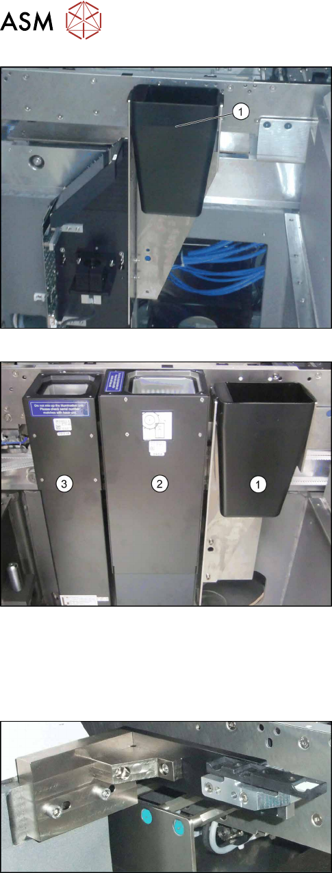
Insert the reject bin
► Insert the reject bin (1) (shown using example of
location 1).
Insert the reject bin
► Hook the reject bin (1) into the bracket next to the
IC camera (2) and the FC camera (3) (shown us-
ing example of location 3).
3.7 Fitting the Calibration Part Holder to the X4i S
Machines of types X3 S and X4 S already have the calibration part holder prefitted. Machines of
type X4i S need to have this retrofitted.
Calibration part holder
► Fit the calibration part holder to all locations at
which a stationary camera has been installed in
type X4i S machines.
3 Installation
3.8 Performing Final Work
Assembly Instructions / Montageanleitung SIPLACE X-Series S Stationary Camera Type 25/33 Stationäre Kamera
Typ 25/33 06/2016
103
3.8 Performing Final Work
► If you have inserted the "reject bin for TwinHead" [03072806-xx], hook the waste tape chute
back into place.
3.8.1 Machines of Types X3 S and X4 S
► Remove any objects from the travel range of the gantry and placement head.
► Start the machine and move the component trolley back into the machine.
► Continue by calibrating the camera(s).
3.8.2 Type X4i S Machines
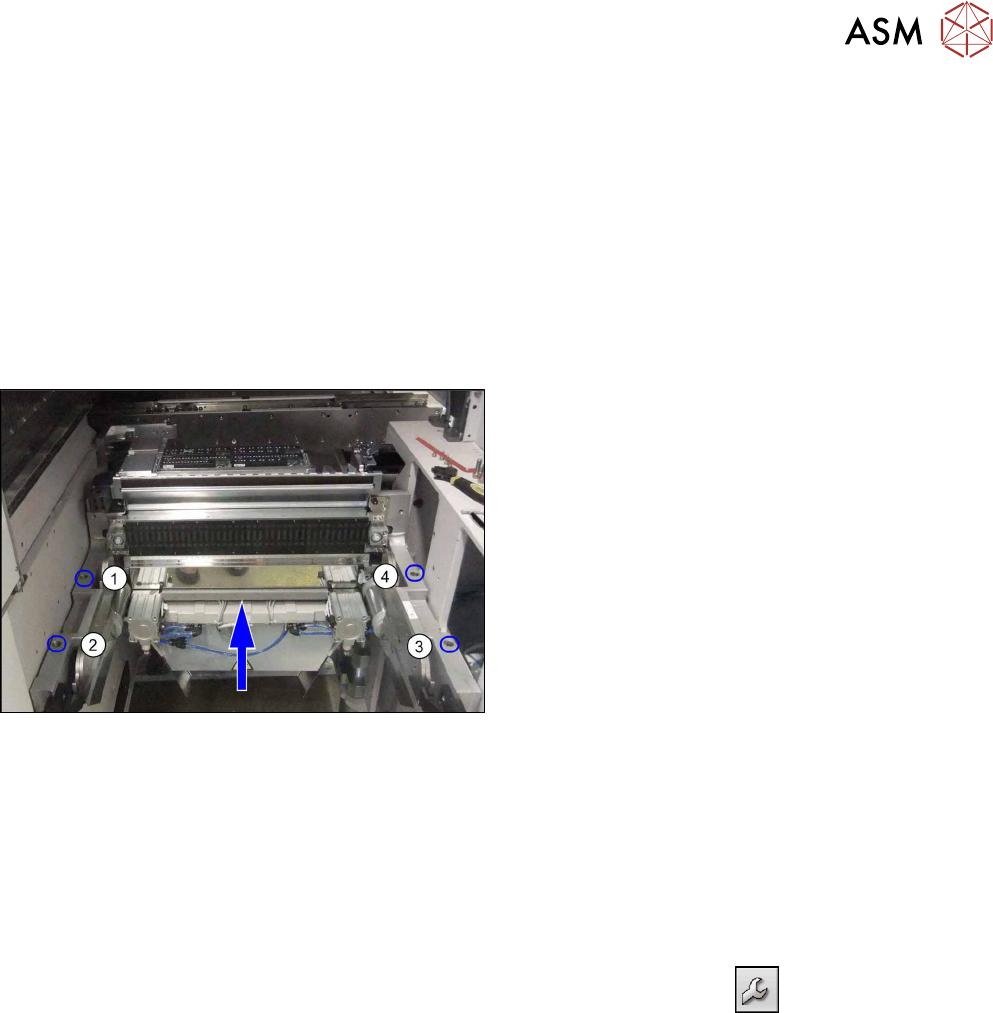
Fitting the COT insert
► Push the COT insert exactly to the second table
position and screw tight at positions (1) to (4).
► Hook the waste tape chute back into place.
► Reinsert the side cover and fix into place.
► Remove any objects from the travel range of the gantry and placement head.
► Start the machine and move the component trolley back into the machine.
► Continue by calibrating the camera(s).
3.8.3 Calibrating the camera (SR70x.xx)
► Switch over to operator level SIPLACE (customer).
► Select Service (configure, update and calibrate the machine)
--> Machine cali-
bration.
► Select Head and cameras and click on Next.
► Select the relevant Gantry and click on Next.
► In the next step, the preconditions are checked. If these are fulfilled, click on Start.
3.9 Software Settings
See: 4.2 "Configuration of Stationary Camera with SIPLACE PRO" [}105]

3 Installation
3.9 Software Settings
104 Assembly Instructions / Montageanleitung SIPLACE X-Series S Stationary Camera Type 25/33 Stationäre Kamera
Typ 25/33 06/2016