00197397-02_AI_Stationary_Camera_25_33_X-Serie-S_to_Gxxxx_DE_EN.pdf - 第62页
1 Introduction 1.1 Safety Instructions 62 Assembly Instructions / Montageanleitung SIPLACE X-Series S Stationary Camera Type 25/33 Stationäre Kamera Typ 25/33 06/2016 1.1.7 Safety Instructions on Hazardous Materials CAUT…
1 Introduction
1.1 Safety Instructions
Assembly Instructions / Montageanleitung SIPLACE X-Series S Stationary Camera Type 25/33 Stationäre Kamera
Typ 25/33 06/2016
61
Maintaining, Installing or Removing Assemblies
► End all placement operations on the machine.
► Shut down the Windows operating system correctly, otherwise problems may occur when re-
starting or data may be lost.
► Switch the machine off at the main switch.
► Disconnect the machine from the main power supply.
► Switch off the machine and attach warnings signs to indicate that service work is in progress.
1.1.4 Safety instructions for the compressed air supply
CAUTION
Risk of injury from compressed air!
Risk of injury when disconnecting the compressed air lines.
► NEVER disconnect compressed air lines while they are still pressurized.
CAUTION
Prolonged interruptions to the compressed air supply can cause damage.
When the machine is switched on, do not use the shutoff valve to interrupt the compressed
air supply for more than 30 minutes.
► If you need to shut off the compressed air system for longer in order to carry out your
work, you must switch the placement system off at the main switch and disconnect it
from the power supply.
1.1.5 Safety Instructions for Work on the Cutting Device
WARNING
Risk of injury when working near the tape cutter.
When working in the area of the tape cutter, move the component trolley out of the machine
and disconnect the machine from the mains supply and the compressed air supply.
► Wait until the operating pressure has dropped to 0 MPa.
► Always secure the machine against unauthorized reactivation.
► Do not reach into the tape cutter.
CAUTION
Risk of injury when performing service work on the tape cutter.
Never support the tape cutter on your body, e.g., on your knees or thighs. Do not place
your feet under the tape cutter.
► Wear appropriately thick protective gloves.
► When removing/fitting the tape cutter, hold it only on the left and right, on the outside.
1.1.6 Safety Instructions for the Gantry
CAUTION
Moving the gantry can damage the placement head.
When moving the gantry, observe the following:
► NEVER move the gantry by pushing with your hands against the placement head.
► NEVER push the gantry while the Z axis is lowered.
1 Introduction
1.1 Safety Instructions
62 Assembly Instructions / Montageanleitung SIPLACE X-Series S Stationary Camera Type 25/33 Stationäre Kamera
Typ 25/33 06/2016
1.1.7 Safety Instructions on Hazardous Materials
CAUTION
Observe the safety data sheets
Observe the applicable safety data sheet, when handling hazardous materials (e. g. Loctite
241, ethanol).
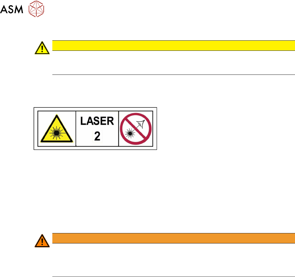
1.1.8 Classification of the Optical Systems
1.1.8.1 Classification of the Whole Machine
The ready-to-operate overall machine is assigned
to laser class2.
The laser classes are determined according to
DIN EN 60825-1:2014.
1.1.8.2 Laser Classification
The following modules are assigned to the laser class 2:
●
PCB barcode scanner
●
Component sensor on the SpeedStar
●
Component sensor on the MultiStar
●
Laser light barriers at the board conveyor
1.1.8.3 Classification of the Camera Systems
WARNING
LEDs
The camera illumination systems are fitted with light LEDs. These are assigned to risk
group 1 according to IEC 62741:2006.
► Do not look into beam!
1 Introduction
1.2 Preparatory Work...
Assembly Instructions / Montageanleitung SIPLACE X-Series S Stationary Camera Type 25/33 Stationäre Kamera
Typ 25/33 06/2016
63
1.2 Preparatory Work...
Purpose and scope
Before performing any preventive maintenance work, conversion work or service work, a procedure
of locking and tagging must be followed and warning signs must be attached if not stated other-
wise. If it is not necessary to switch off the machine, it is explicitly mentioned.
The procedure, when followed correctly, eliminates the possibility of an employee being injured.
NOTICE
Additional safety measures
This procedure represents the minimum lock out and tag out requirements for the machine
during preventive maintenance work and service work. Any additional safeguards needed
to complete work safely can be specified by facilities supervision, the safety officer, the
safety committee and the health department.
Description
Whenever it becomes necessary to isolate, control and release energy, the following procedure is
to be followed.
► Notify all affected employees.
► Switch off the machine and all additional devices. Carry out all normal stopping procedures:
ð Press the STOP button.
ð Shut down the station computer.
ð Switch off the machine using the main switch.
► Isolate the machine from all its energy sources:
ð Shut off the compressed air supply.
ð Shut off the main power supply.
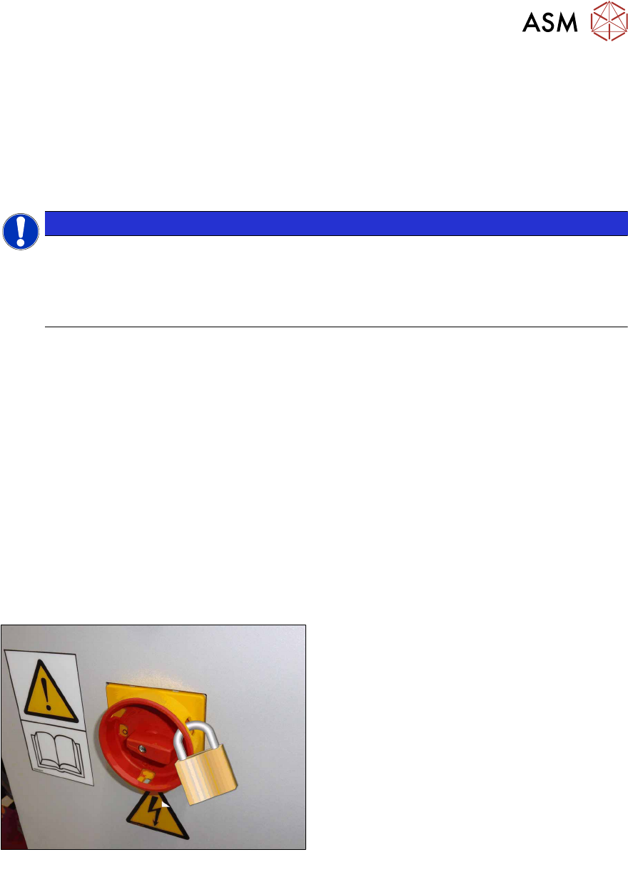
► Lock out the machine.
ð Attach a lock wherever possible:
Fig.1: Attaching a padlock to the main power switch
Secure Main Switch
► Secure the main switch with a padlock.