00197397-02_AI_Stationary_Camera_25_33_X-Serie-S_to_Gxxxx_DE_EN.pdf - 第57页
57 Assembly Instructions / Montageanleitung SIPLACE X-Series S Stationary Camera Type 25/33 Stationäre Kamera Typ 25/33 06/2016 Table of Contents Table of Contents 1 Introduction .. 59 1.1 Safety Instructions .. 59 1…
4 Anhang
4.4 Auszüge aus der Serviceanleitung
56 Assembly Instructions / Montageanleitung SIPLACE X-Series S Stationary Camera Type 25/33 Stationäre Kamera
Typ 25/33 06/2016
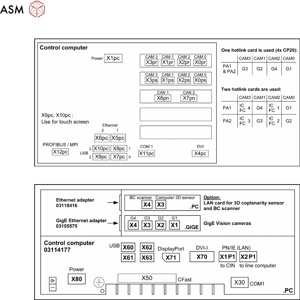
4.4.2 Übersicht Anschlüsse BoxPC 627x/827x
4.4.3 Übersicht Anschlüsse BoxPC 427D

57Assembly Instructions / Montageanleitung SIPLACE X-Series S Stationary Camera Type 25/33 Stationäre Kamera
Typ 25/33 06/2016
Table of Contents
Table of Contents
1 Introduction.. 59
1.1 Safety Instructions.. 59
1.1.1 Conventions for the use of safety instructions.. 59
1.1.2 Safety Instructions for Working with Strong Magnetic Fields.. 60
1.1.3 Safety Instructions for the Power Supply (Without SMPS).. 60
1.1.4 Safety instructions for the compressed air supply.. 61
1.1.5 Safety Instructions for Work on the Cutting Device.. 61
1.1.6 Safety Instructions for the Gantry.. 61
1.1.7 Safety Instructions on Hazardous Materials.. 62
1.1.8 Classification of the Optical Systems.. 62
1.1.8.1 Classification of the Whole Machine.. 62
1.1.8.2 Laser Classification.. 62
1.1.8.3 Classification of the Camera Systems.. 62
1.2 Preparatory Work..... 63
1.3 Other Instructions.. 66
1.3.1 Environmentally-Friendly Disposal of Materials and Components.. 66
1.3.2 Use of Original SIPLACE Accessories and Spare Parts.. 66
1.3.3 ESD Guidelines.. 66
1.3.3.1 Definition of ESD.. 66
1.3.3.2 Important Measures to Protect Against Static Charging.. 66
1.3.3.3 Handling ESD Modules.. 67
1.3.3.4 Measurements and Modifications to ESD Modules.. 67
1.3.3.5 Dispatching ESD Modules.. 67
1.3.4 Release History.. 67
1.4 Staff Qualifications and Training.. 68
2 Brief Description.. 69
2.1 Product Description.. 69
2.1.1 Technical Data... 70
2.1.2 Version Overview.. 70
2.2 Overview of X Series S Machines.. 71
2.3 Requirements.. 71
2.4 Configurations.. 71
2.5 Scope of Delivery.. 72
2.6 Tools and Equipment Required.. 72
2.7 Required Working Time.. 72
3 Installation.. 73
3.1 Performing Preparatory Work.. 73
3.1.1 Type X4i S Machines.. 74
3.1.1.1 Adjusting the Hood.. 74
3.1.1.2 Adjusting the Y Buffer.. 76
3.1.1.3 Adjusting the Hand Guard.. 77
3.1.1.4 Moving the COT Insert Outwards.. 78
3.2 Fitting the Camera.. 81
3.2.1 Adjusting the Camera Jumper Setting.. 82
3.2.1.1 Coding the DIP Switch (8 Pin).. 82
3.2.1.2 Coding the DIP Switch (6 Pin).. 83
3.2.2 Fitting the IC Camera Type 33.. 83

58 Assembly Instructions / Montageanleitung SIPLACE X-Series S Stationary Camera Type 25/33 Stationäre Kamera
Typ 25/33 06/2016
Table of Contents
3.2.2.1 Fitting the Spacer Plates.. 84
3.2.2.2 IC Camera Type 33: Fixing the Camera Module.. 87
3.2.3 FC Camera Type 25 - Locations 2 and 3 - Installation.. 88
3.2.3.1 Fitting the Spacer Plates.. 88
3.2.3.2 Installing the Fiducial Plate.. 90
3.2.3.3 FC Camera Type 25: Fixing the Camera Module.. 90
3.3 Connecting the Cable.. 91
3.3.1 IC Cameras Type 33 From Version 03 to 07.. 91
3.3.1.1 Camera Connection Board VLT33.. 91
3.3.2 FC Cameras Type 25 From Version 03.. 93
3.3.3 FC Cameras Type 25 From Version 05.. 93
3.3.4 Connecting the Hotlink Cable to the Box PC.. 95
3.4 Fitting the Camera Cover.. 96
3.5 Fitting the Component Reject Bin.. 97
3.6 Fitting the Reject Bin Sensor.. 100
3.7 Fitting the Calibration Part Holder to the X4i S.. 102
3.8 Performing Final Work.. 103
3.8.1 Machines of Types X3 S and X4 S.. 103
3.8.2 Type X4i S Machines.. 103
3.8.3 Calibrating the camera (SR70x.xx).. 103
3.9 Software Settings.. 103
4 Appendix.. 105
4.1 Installation Height of the Stationary Camera.. 105
4.1.1 Stationary Camera in Position 1.. 105
4.2 Configuration of Stationary Camera with SIPLACE PRO.. 105
4.3 Circuit Diagrams.. 106
4.3.1 Camera CAN bus.. 106
4.4 Excerpts from the Service Manual.. 107
4.4.1 Installation Positions of COT Insert and Manual Table (Table Positions).. 107
4.4.2 Overview of Connections for BoxPC 627x/827x.. 108
4.4.3 Overview of Connections for BoxPC 427D.. 108