00197397-02_AI_Stationary_Camera_25_33_X-Serie-S_to_Gxxxx_DE_EN.pdf - 第97页
3 Installation 3.5 Fitting the Component Reject Bin Assembly Instructions / Montageanleitung SIPLACE X-Series S Stationary Camera Type 25/33 Stationäre Kamera Typ 25/33 06/2016 97 3.5 Fitting the Component Reject Bin Whe…
3 Installation
3.4 Fitting the Camera Cover
96 Assembly Instructions / Montageanleitung SIPLACE X-Series S Stationary Camera Type 25/33 Stationäre Kamera
Typ 25/33 06/2016
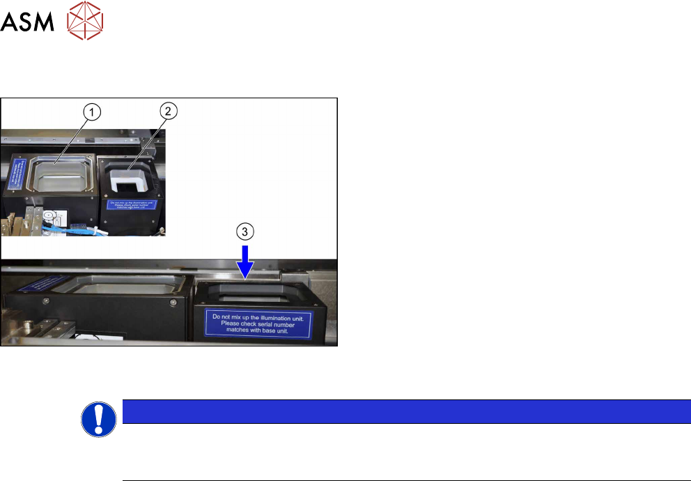
3.4 Fitting the Camera Cover
Camera cover (shown here using the example of loca-
tion 2 with an IC camera (1) and an FC camera (2))
► Hook in the housing for the lower section of the
camera.
► Carefully place the camera upper section (illumin-
ation unit) onto the camera lower section.
► Check whether the camera upper section has
been pushed in to the end stop.
ð At location 1 to 4, the upper edge of the cam-
era must be approx. 5 mm under the upper
edge of the board conveyor (3).
► Make sure that the glass surface is clean. Clean
the mirror/glass surface with a microfiber cloth, if
necessary.
NOTICE
Exchanging the camera housing when there is more than one camera.
When fitting the cover and the lighting unit, make sure that this is not confused with the one
for a different camera.
3 Installation
3.5 Fitting the Component Reject Bin
Assembly Instructions / Montageanleitung SIPLACE X-Series S Stationary Camera Type 25/33 Stationäre Kamera
Typ 25/33 06/2016
97
3.5 Fitting the Component Reject Bin
When using the "stationary camera for CPP head" option, you need to fit an additional reject bin for
components >36x36mm. This is identical to the TwinHead reject bin.
This reject bin is included in the delivery packages for the stationary camera and the HRK for Twin-
Head.
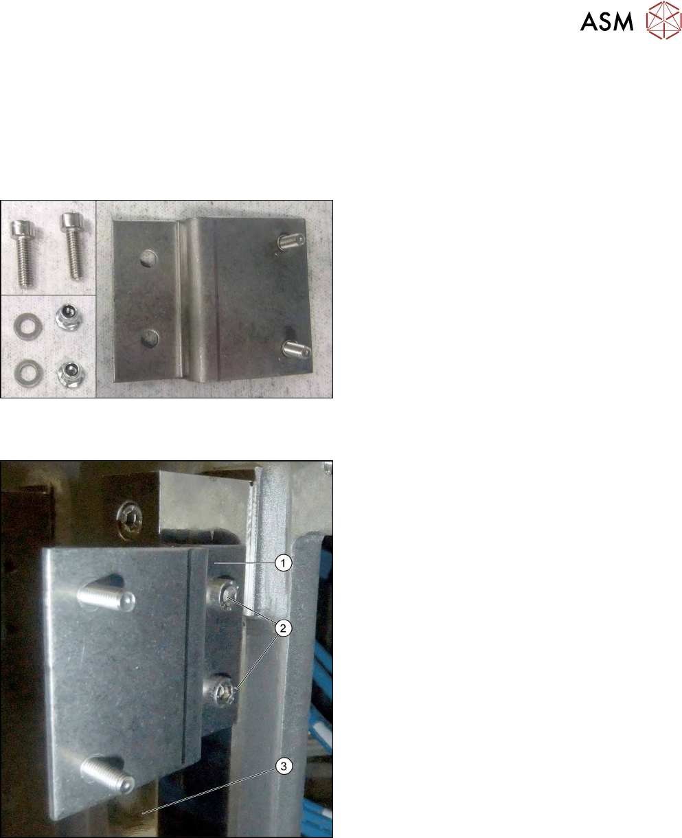
Parts required for location 1 and 4
Parts
Angled bracket and fixtures for reject bin at location 1
and 4
Installation at location 1 and 4
Fitting the angled bracket
► Fix the angled bracket (1) into place using two
M6x12 screws [03042572-xx] to the angled
bracket (2) on the right-hand side of the spacer
plate (3).
3 Installation
3.5 Fitting the Component Reject Bin
98 Assembly Instructions / Montageanleitung SIPLACE X-Series S Stationary Camera Type 25/33 Stationäre Kamera
Typ 25/33 06/2016
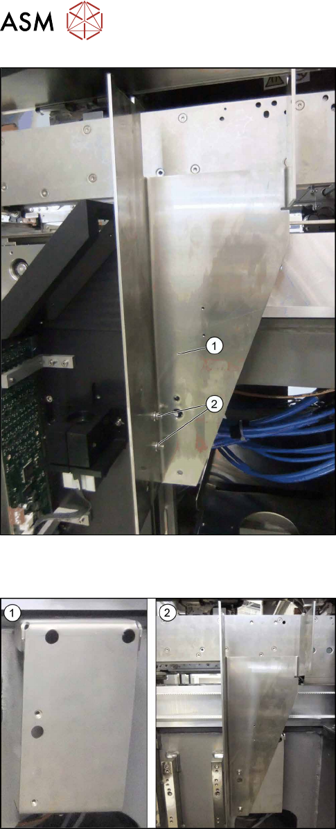
Fitting the reject bin holder
► Fix the bracket for the reject bin (1) into place us-
ing two M5 nuts (self-fixing with flange, turnable)
(2).
► Continue by fitting the sensor query reject bin
(see 3.6 "Fitting the Reject Bin Sensor" [}100].
Parts required for location 2 and 3
Parts
1. Left: retaining plate for the reject bin bracket at
location 2 and 3
2. Right: reject bin bracket