00197397-02_AI_Stationary_Camera_25_33_X-Serie-S_to_Gxxxx_DE_EN.pdf - 第95页
3 Installation 3.3 Connecting the Cable Assembly Instructions / Montageanleitung SIPLACE X-Series S Stationary Camera Type 25/33 Stationäre Kamera Typ 25/33 06/2016 95 3.3.4 Connecting the Hotlink Cable to the Box PC CAU…
3 Installation
3.3 Connecting the Cable
94 Assembly Instructions / Montageanleitung SIPLACE X-Series S Stationary Camera Type 25/33 Stationäre Kamera
Typ 25/33 06/2016
Connection to FC cameras (type 25 with version 05)
If there is a version 05 FC camera present, the IC camera will be connected to this. From this ver-
sion onwards, the FC camera has a multiplexer, which provides the connections for the IC and FC
cameras. This enables you to operate a placement area with up to four stationary cameras.
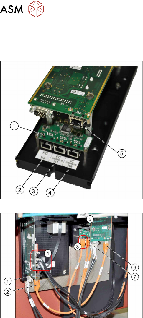
Camera connections
1. Multiplexer
2. BoxPC input
3. Output for type 25 camera (FC camera)
4. Output for type 33/36 camera (IC camera)
5. Camera input
The multiplexer makes it possible to directly connect a
stationary camera (type 33/36) to the other stationary
camera (type 25).
Connect the cameras (example of SX1 shown here)
► Disconnect the camera cable coming from the
box PC at the FC camera driver board (6) and re-
connect it to the multiplexer connection labeled
PC.
► Underneath the FC camera you will find two un-
used, short camera cables and the power supply
cable [03055298‑xx], fixed with a cable tie to the
support plate. Use one short camera cable for the
connection between the multiplexer and the IC
camera (2) and the other one for the connection
between the multiplexer and the FC camera
driver board(6).
► Connect the power supply with the cable from the
retrofitting kit. To do this, connect the power sup-
ply cable [03055298‑xx] to connection X4 or X5
on the IC camera driver board(4) and to connec-
tion X4 on the FC camera(5).
► Connect the CAN bus to connections(1) and(7).
► Fix the incoming cables (camera bus, CAN bus, power supply) with the fastening element
[00316830-xx] and cable ties [00805141-xx] underneath the camera.
3 Installation
3.3 Connecting the Cable
Assembly Instructions / Montageanleitung SIPLACE X-Series S Stationary Camera Type 25/33 Stationäre Kamera
Typ 25/33 06/2016
95
3.3.4 Connecting the Hotlink Cable to the Box PC
CAUTION
Never connect a LAN cable to the hotlink card!
This could damage the hotlink card.
NOTICE
Connection for stationary cameras
► Observe section and the latest circuit diagrams for your machine.
► When installed, the version of your hotlink card can only be determined by the position
of the camera connection label and the order of CAM connections.
► The stationary cameras are always connected to CAM2 or CAM3.
► The camera cables are labeled with their relevant connection details according to the
pattern X*p*.
ð Machines with only C&P20A heads will only have one hotlink card fitted. When
converting to a CPP or Twin Head, you need to install an additional "hotlink inter-
face PCI-A24-K01" [03052135Sxx] in the Box PC. Observe the currently applicable
service manual for your machine.
► All hotlink cables must be run from the relevant location to the Box PC.
► Connect your camera cable as follows:
CAUTION
Correctly connecting the camera cable
► Make sure that you connect the cameras correctly. Observe the labels on the hotlink
cards. If you do not observe this, placement performance may be adversely affected.
Pay particular attention to the different order of connections on the PCI-A24!
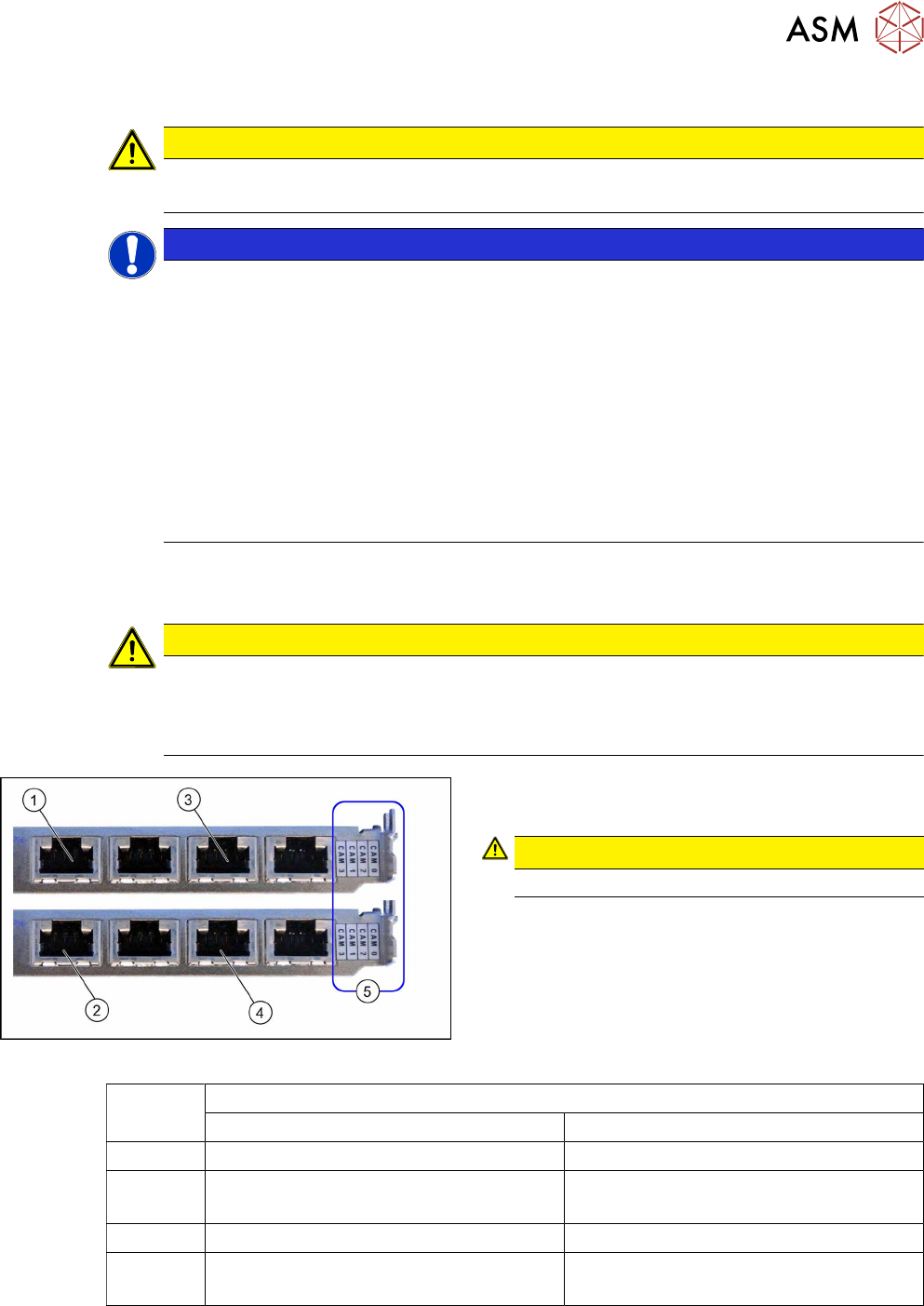
Hotlink card
Hotlink card (PCI-A24 [03052135-xx])
The hotlink card is fitted in the SX4 as a default.
CAUTION!
Observe the order of camera connections (5)!
.
(1) and (3): Stationary cameras for placement area 1
(X2pr and X3pr)
(2) and (4): Stationary cameras for placement area 2
(X2ps and X3ps)
Hotlink cards
Card 1 (top) Card 2 (bottom)
CAM0 Gantry 1 - PCB/component camera Gantry 2 - PCB/component camera
CAM1 Gantry 1 - stationary cameras (IC/FC)
[03077048-xx] → cable X1ps
Gantry 2 - stationary cameras (IC/FC)
[03077048-xx] → cable X2ps
CAM2 Gantry 4 - PCB/component camera Gantry 3 - PCB/component camera
CAM3 Gantry 4 - stationary cameras (IC/FC)
[03077049-xx] → cable X4ps
Gantry 3 - stationary cameras (IC/FC)
[03077049-xx] → cable X3ps
3 Installation
3.4 Fitting the Camera Cover
96 Assembly Instructions / Montageanleitung SIPLACE X-Series S Stationary Camera Type 25/33 Stationäre Kamera
Typ 25/33 06/2016
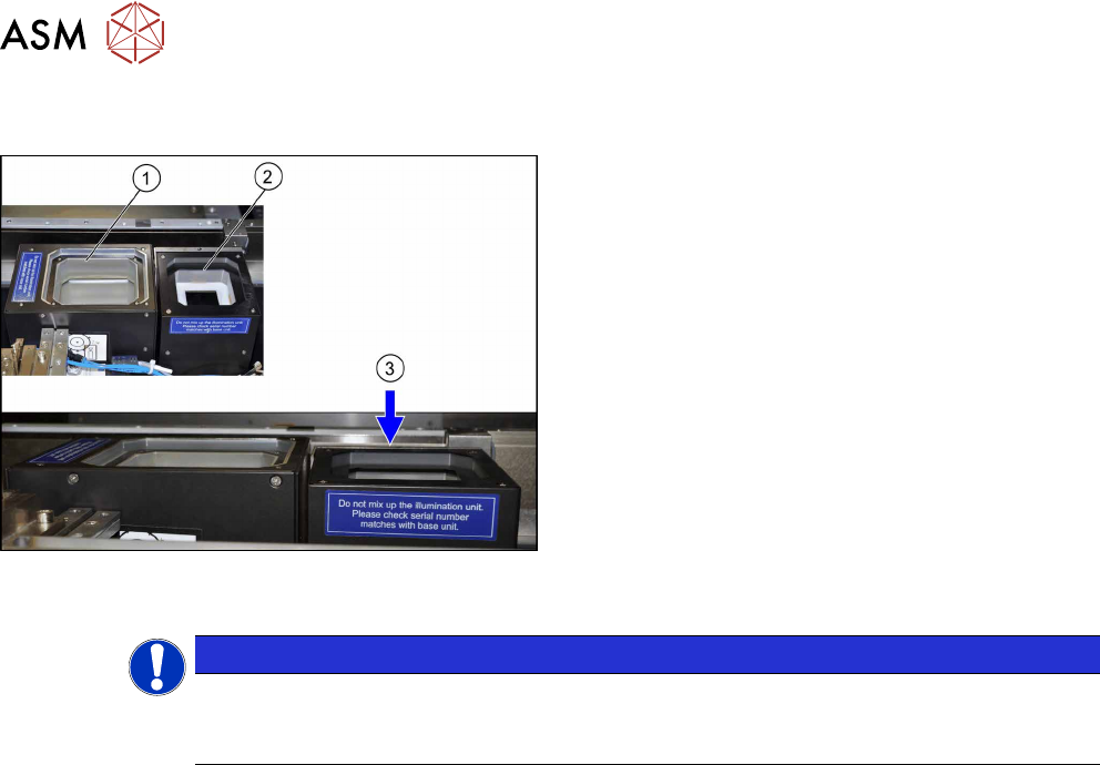
3.4 Fitting the Camera Cover
Camera cover (shown here using the example of loca-
tion 2 with an IC camera (1) and an FC camera (2))
► Hook in the housing for the lower section of the
camera.
► Carefully place the camera upper section (illumin-
ation unit) onto the camera lower section.
► Check whether the camera upper section has
been pushed in to the end stop.
ð At location 1 to 4, the upper edge of the cam-
era must be approx. 5 mm under the upper
edge of the board conveyor (3).
► Make sure that the glass surface is clean. Clean
the mirror/glass surface with a microfiber cloth, if
necessary.
NOTICE
Exchanging the camera housing when there is more than one camera.
When fitting the cover and the lighting unit, make sure that this is not confused with the one
for a different camera.