00197397-02_AI_Stationary_Camera_25_33_X-Serie-S_to_Gxxxx_DE_EN.pdf - 第93页
3 Installation 3.3 Connecting the Cable Assembly Instructions / Montageanleitung SIPLACE X-Series S Stationary Camera Type 25/33 Stationäre Kamera Typ 25/33 06/2016 93 3.3.2 FC Cameras Type 25 From Version 03 General In …
3 Installation
3.3 Connecting the Cable
92 Assembly Instructions / Montageanleitung SIPLACE X-Series S Stationary Camera Type 25/33 Stationäre Kamera
Typ 25/33 06/2016
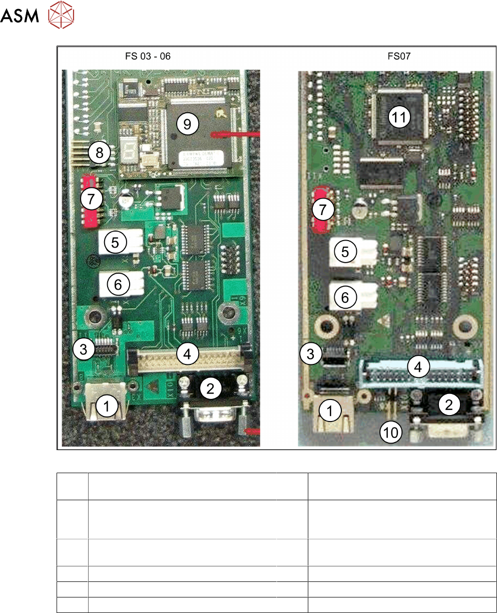
Fig.9: Vision LED driver board VLT33 from FS03
1 X3: Camera bus to station computer hot-
link card
2 CAN bus
3 Not relevant 4 Vision cable 34-pin IC camera
[03003439-xx] to Vision controller
For machines up to serial number B326
5 X4: Cable for power supply 6 X5: Cable for power supply
Bridge to FC camera
7 DIP switch 8 Not relevant
9 Controller plug-in card FS03 to FS06 10 Not relevant
11 Controller onboard from FS07
3 Installation
3.3 Connecting the Cable
Assembly Instructions / Montageanleitung SIPLACE X-Series S Stationary Camera Type 25/33 Stationäre Kamera
Typ 25/33 06/2016
93
3.3.2 FC Cameras Type 25 From Version 03
General
In cameras with function state -03, the CAN controller is located directly on the driver board.
NOTICE
Coding the DIP switch
Depending on the type series, the camera for the coding either has an 8 pin or 6 pin DIP
switch in it.
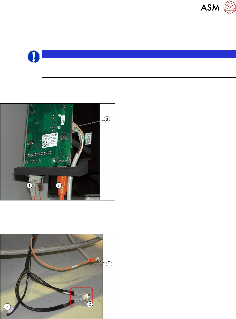
Camera connections
For independent operation, the camera cable, the CAN bus cable and the power supply are con-
nected.
Camera connections
1. CAN bus
2. Camera cable (hotlink cable)
3. Cable for power supply
3.3.3 FC Cameras Type 25 From Version 05
Direct connection to the machine
Camera connections
1. Camera cable (hotlink cable)
2. 2 x CAN bus cable (For IC and FC camera)
3. Power Supply
The opening in the machine frame contains two CAN
bus cables (2), the camera cable (1) (hotlink cable)
and the power supply cable (3).
► Connect the camera cable (1), the CAN bus
cable (2) and the power supply cable (3) to the
stationary camera, according to the respective
camera configuration.
3 Installation
3.3 Connecting the Cable
94 Assembly Instructions / Montageanleitung SIPLACE X-Series S Stationary Camera Type 25/33 Stationäre Kamera
Typ 25/33 06/2016
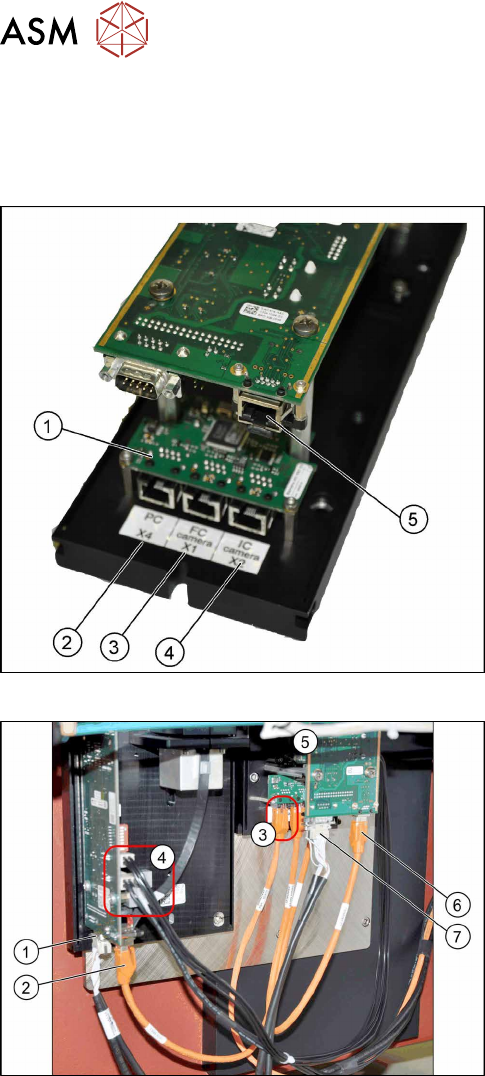
Connection to FC cameras (type 25 with version 05)
If there is a version 05 FC camera present, the IC camera will be connected to this. From this ver-
sion onwards, the FC camera has a multiplexer, which provides the connections for the IC and FC
cameras. This enables you to operate a placement area with up to four stationary cameras.
Camera connections
1. Multiplexer
2. BoxPC input
3. Output for type 25 camera (FC camera)
4. Output for type 33/36 camera (IC camera)
5. Camera input
The multiplexer makes it possible to directly connect a
stationary camera (type 33/36) to the other stationary
camera (type 25).
Connect the cameras (example of SX1 shown here)
► Disconnect the camera cable coming from the
box PC at the FC camera driver board (6) and re-
connect it to the multiplexer connection labeled
PC.
► Underneath the FC camera you will find two un-
used, short camera cables and the power supply
cable [03055298‑xx], fixed with a cable tie to the
support plate. Use one short camera cable for the
connection between the multiplexer and the IC
camera (2) and the other one for the connection
between the multiplexer and the FC camera
driver board(6).
► Connect the power supply with the cable from the
retrofitting kit. To do this, connect the power sup-
ply cable [03055298‑xx] to connection X4 or X5
on the IC camera driver board(4) and to connec-
tion X4 on the FC camera(5).
► Connect the CAN bus to connections(1) and(7).
► Fix the incoming cables (camera bus, CAN bus, power supply) with the fastening element
[00316830-xx] and cable ties [00805141-xx] underneath the camera.