00197397-02_AI_Stationary_Camera_25_33_X-Serie-S_to_Gxxxx_DE_EN.pdf - 第68页
1 Introduction 1.4 Staff Qualifications and Training 68 Assembly Instructions / Montageanleitung SIPLACE X-Series S Stationary Camera Type 25/33 Stationäre Kamera Typ 25/33 06/2016 1.4 Staff Qualifications and Training Q…

1 Introduction
1.3 Other Instructions
Assembly Instructions / Montageanleitung SIPLACE X-Series S Stationary Camera Type 25/33 Stationäre Kamera
Typ 25/33 06/2016
67
1.3.3.3 Handling ESD Modules
Do not touch electronic modules unless it is absolutely essential to do so in order to carry out other
work. If it is necessary, make sure that you do not touch the pins or printed conductors when you
pick up flat modules.
Do not touch components unless
●
You are constantly earthed by an ESD wrist strap or
●
You are wearing ESD shoes or ESD shoe earthing strips on an ESD floor.
Always discharge yourself before you touch an electronic module. To do this, simply touch a con-
ductive and earthed object immediately before you touch the module (such as unpainted parts of a
switch cabinet, a water pipe, etc.).
Do not allow modules with chargeable and highly insulating materials to touch one another, e.g.
plastic films, insulating table surfaces or items of clothing made from synthetic fibers.
Always place the modules on a conductive surface (table with an ESD coating, conductive ESD
foam, ESD bag or container).
Do not bring modules near visual display units, monitors or televisions. Keep them at least 10cm
away from the screen.
1.3.3.4 Measurements and Modifications to ESD Modules
Measurements of the assemblies may only be taken if
●
The measuring device has been grounded (e.g. via protective conductor) or
●
you discharge the measuring head before taking measurements with a potential-free measur-
ing device (e.g. by touching an unpainted metal part of the controller casing).
► Always use an earthed soldering iron if you carry out any soldering work.
1.3.3.5 Dispatching ESD Modules
► Always store modules and components in conductive packaging (e.g. metalized plastic bags
or metal sleeves) and dispatch them in conductive packaging.
► If the packaging is not conductive, place the modules in a conductive envelope before pack-
aging. Use conductive expanded rubber, ESD bags, domestic aluminum foil or paper, for ex-
ample.
► If the module has integral batteries, ensure that the conductive packaging does not touch or
short-circuit the battery terminals and, if necessary, first cover the terminals with insulating
tape or material.
1.3.4 Release History
Document
SIPLACE X-Series S
Stationary camera type 25/33
Assembly Instructions
Edition Amendments
05/2013 First edition
06/2016 Amendments, supplements:
●
Scope of delivery
●
Fiducial plate
●
Spacer plates
●
Corrections in chapters "2.4 Configurations" and "3.2 Fitting the Camera"

1 Introduction
1.4 Staff Qualifications and Training
68 Assembly Instructions / Montageanleitung SIPLACE X-Series S Stationary Camera Type 25/33 Stationäre Kamera
Typ 25/33 06/2016
1.4 Staff Qualifications and Training
Qualified or adequately trained personnel means that these people are familiar with the setting up,
operation and maintenance of the machine and the add-on devices and are suitably qualified, e.g.:
●
Have been trained, instructed or authorized to switch on and off, isolate, earth and identify
electrical circuits and system components in accordance with normal safety standards.
●
Have been trained or instructed in the upkeep and use of appropriate safety equipment in
accordance with normal safety standards.
●
Have received first aid training.
2 Brief Description
2.1 Product Description
Assembly Instructions / Montageanleitung SIPLACE X-Series S Stationary Camera Type 25/33 Stationäre Kamera
Typ 25/33 06/2016
69
2 Brief Description
2.1 Product Description
X-Series S machines with machine numbers up to Gxxxx can optionally accommodate one or two
stationary cameras "IC camera type 33" or "FC camera type 25". Only stationary cameras without
GigE can be used.
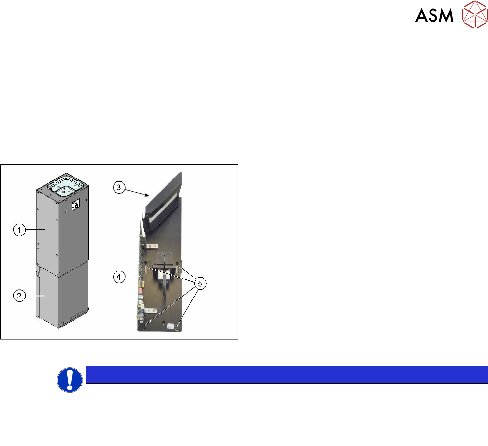
Camera design
Example of type 33 shown
Stationary camera design
1. Upper section of camera (illumination unit)
2. Lower section of camera
3. Mirror
4. Camera electronics
5. Holes for fastening screws
NOTICE
The camera upper section has a fixed assignment to the camera lower section.
The camera upper section may not be used with another camera lower section. Both the
upper and lower sections are mechanically and electrically coordinated and may not be ex-
changed for use with other cameras. The serial and version numbers of the top and bottom
sections of the camera must be identical.