00197397-02_AI_Stationary_Camera_25_33_X-Serie-S_to_Gxxxx_DE_EN.pdf - 第90页
3 Installation 3.2 Fitting the Camera 90 Assembly Instructions / Montageanleitung SIPLACE X-Series S Stationary Camera Type 25/33 Stationäre Kamera Typ 25/33 06/2016 Fitting the spacer plates ► Use the screws (M6x45) to …
3 Installation
3.2 Fitting the Camera
Assembly Instructions / Montageanleitung SIPLACE X-Series S Stationary Camera Type 25/33 Stationäre Kamera
Typ 25/33 06/2016
89
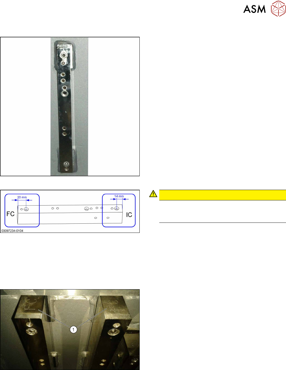
Spacer plates for locations 2 and 3
Distance plate
Narrow spacer plates for locations 2 and 3
Correct labeling of spacer plates
CAUTION!
Incorrect labeling
In a few cases, these spacer plates are supplied
with incorrect labeling.
.
► Compare your spacer plates with the diagram.
If the label does not match the diagram, correct
the label.
●
– FC: This side must be on top for FC cameras
and Q10 magazines (Smart Pin Support).
– IC: This side must be on top for IC cameras.
Fitting the spacer plates
FC top
IC and FC are marked on the top and bottom of the
spacer plates.
When fitting an FC camera, make sure that the FC let-
tering (1) faces upwards.
3 Installation
3.2 Fitting the Camera
90 Assembly Instructions / Montageanleitung SIPLACE X-Series S Stationary Camera Type 25/33 Stationäre Kamera
Typ 25/33 06/2016
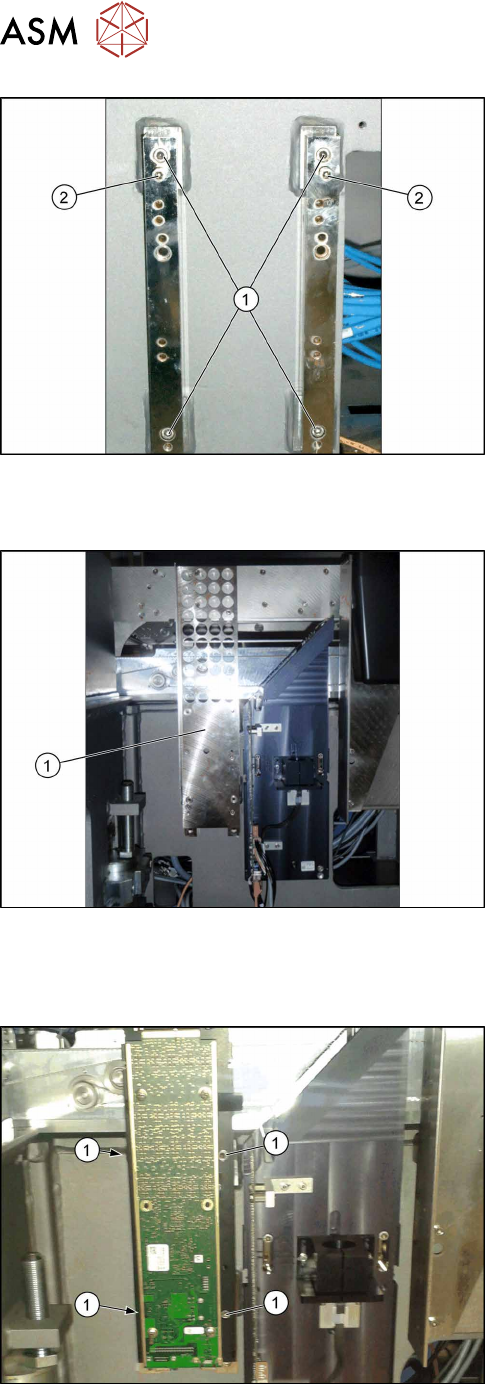
Fitting the spacer plates
► Use the screws (M6x45) to fix the spacer plates to
the screw fixing points in the machine frame (1).
Make sure that the FC label indicates upwards.
► At position (2), tighten the two screws M6x25
[03042575-xx] for the camera suspension holder,
until the screw shaft protrudes approx. 15mm
above the mount.
3.2.3.2 Installing the Fiducial Plate
Fiducial plate (example of X-Series S up to number
Gxxxx shown)
► Fit the fiducial plate [03077911‑xx] with four
fastening screws M6x12 [03045087‑xx].
3.2.3.3 FC Camera Type 25: Fixing the Camera Module
Position the camera
► Position the camera on the spacer plates and fix
it directly with 2 x M6x25 [03042575-xx] screws
(1) on each side.
Locations 2 and 3
► Continue by attaching the camera cables (see section 3.3 "Connecting the Cable" [}91]).
3 Installation
3.3 Connecting the Cable
Assembly Instructions / Montageanleitung SIPLACE X-Series S Stationary Camera Type 25/33 Stationäre Kamera
Typ 25/33 06/2016
91
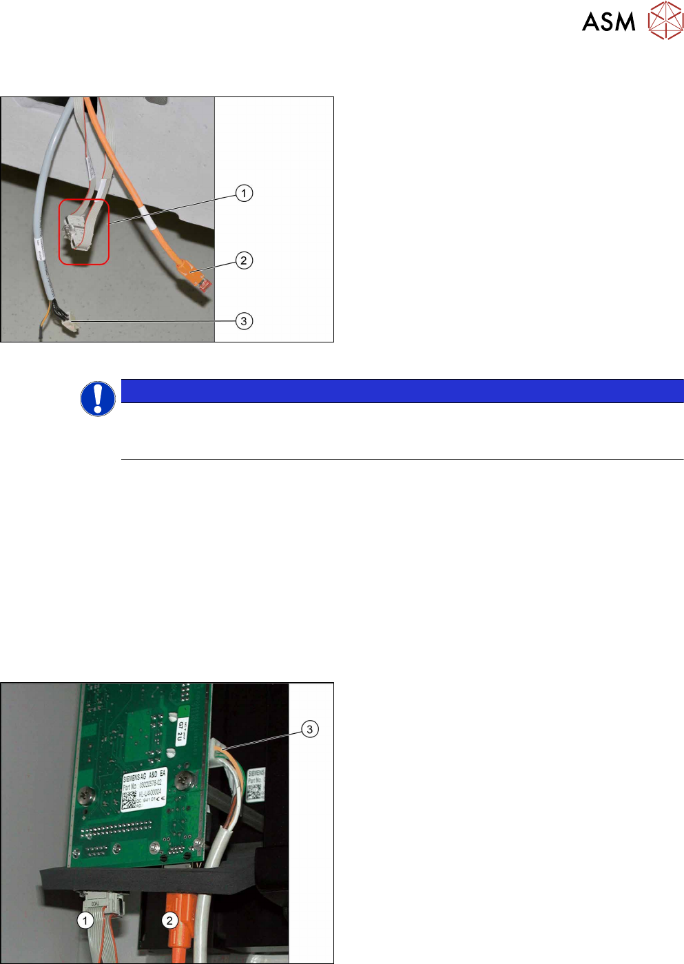
3.3 Connecting the Cable
Electrical connections
1. CAN bus cable
2. Camera cable (hotlink cable, orange)
3. Power Supply
The opening in the machine frame contains the CAN
bus cable (1), the camera cable (2) (hotlink cable) and
the power supply cable (3). The CAN bus cable is con-
nected together (CAN bus loop). The CAN bus cable
[03050550-xx] supplied in the retrofitting kit is used to
connect the CAN bus cable (1) to the camera.
NOTICE
Connection of IC and FC camera.
FC cameras of type 25 are equipped with a multiplexer from version 05 onwards. When fit-
ting an IC and an FC camera at location 2 or 3, both cameras are switched in series.
3.3.1 IC Cameras Type 33 From Version 03 to 07
The way in which the IC camera type 33 is connected depends on whether it is the only camera at
a location or whether it is being used in combination with an FC camera type 25.
For solitary use at one location, see section 3.3.1.1 "Camera Connection Board VLT33" [}91].
For use in combination with an FC camera type 25, go to section 3.3.3 "FC Cameras Type 25 From
Version 05" [}93] for details about how to connect an FC camera type 25.
General
In these cameras, the CAN controller is located directly on the driver board.
3.3.1.1 Camera Connection Board VLT33
Camera connections
For independent operation, the camera cable, the
CAN bus cable and the power supply cable are con-
nected directly.
1. CAN bus
2. Camera cable (hotlink cable)
3. Cable for power supply
► Connect the power supply cable, CAN bus cable
and camera cable to the camera.