00197397-02_AI_Stationary_Camera_25_33_X-Serie-S_to_Gxxxx_DE_EN.pdf - 第88页
3 Installation 3.2 Fitting the Camera 88 Assembly Instructions / Montageanleitung SIPLACE X-Series S Stationary Camera Type 25/33 Stationäre Kamera Typ 25/33 06/2016 3.2.3 FC Camera Type 25 - Locations 2 and 3 - Installa…
3 Installation
3.2 Fitting the Camera
Assembly Instructions / Montageanleitung SIPLACE X-Series S Stationary Camera Type 25/33 Stationäre Kamera
Typ 25/33 06/2016
87
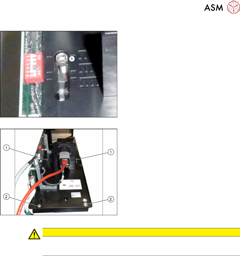
3.2.2.2 IC Camera Type 33: Fixing the Camera Module
Markings for different installation heights (1)
► Hook the camera on its screws onto the spacer
plates.
Lower section of camera
► Hook the upper holes (1) on the lower section of
the camera onto these two screws. (key hole
principle for cameras of type 33 from version 06.)
► Use the two lower screws (2) to adjust the lower
section of the camera to the correct installation
height at position I (1) and tighten all four screws.
CAUTION
Observe the installation height
When fitting the camera, observe the correct installation height. Otherwise there is the
danger of a crash!
Locations 2 and 3
► If you do not have to install an FC camera at the same location, continue by attaching the
camera cables (see section 3.3 "Connecting the Cable" [}91]).
► If you need to install an FC camera at the same location, continue with section 3.2.3 "FC Cam-
era Type 25 - Locations 2 and 3 - Installation" [}88]
Locations 1 and 4
► Continue by attaching the camera cables (see section 3.3 "Connecting the Cable" [}91]).
3 Installation
3.2 Fitting the Camera
88 Assembly Instructions / Montageanleitung SIPLACE X-Series S Stationary Camera Type 25/33 Stationäre Kamera
Typ 25/33 06/2016
3.2.3 FC Camera Type 25 - Locations 2 and 3 - Installation
FC cameras of type 25 can only be fitted at locations 2 and 3, alone or in combination with an IC
camera of type 33.
The camera is fixed at two spacer plates, which have already been screwed to the screw fixing
points on the machine base.
The procedure for fitting these spacer plates and for fixing the camera is in principle the same at
both locations. Any differences are indicated in the following section.
► Before installation, make sure that the jumper setting for the camera to be fitted is correct (see
3.2.1 "Adjusting the Camera Jumper Setting" [}82]).
3.2.3.1 Fitting the Spacer Plates
The spacer plates are fixed to the relevant screw fixing points in the machine base. Narrow spacer
plates are used at locations 2 and 3.
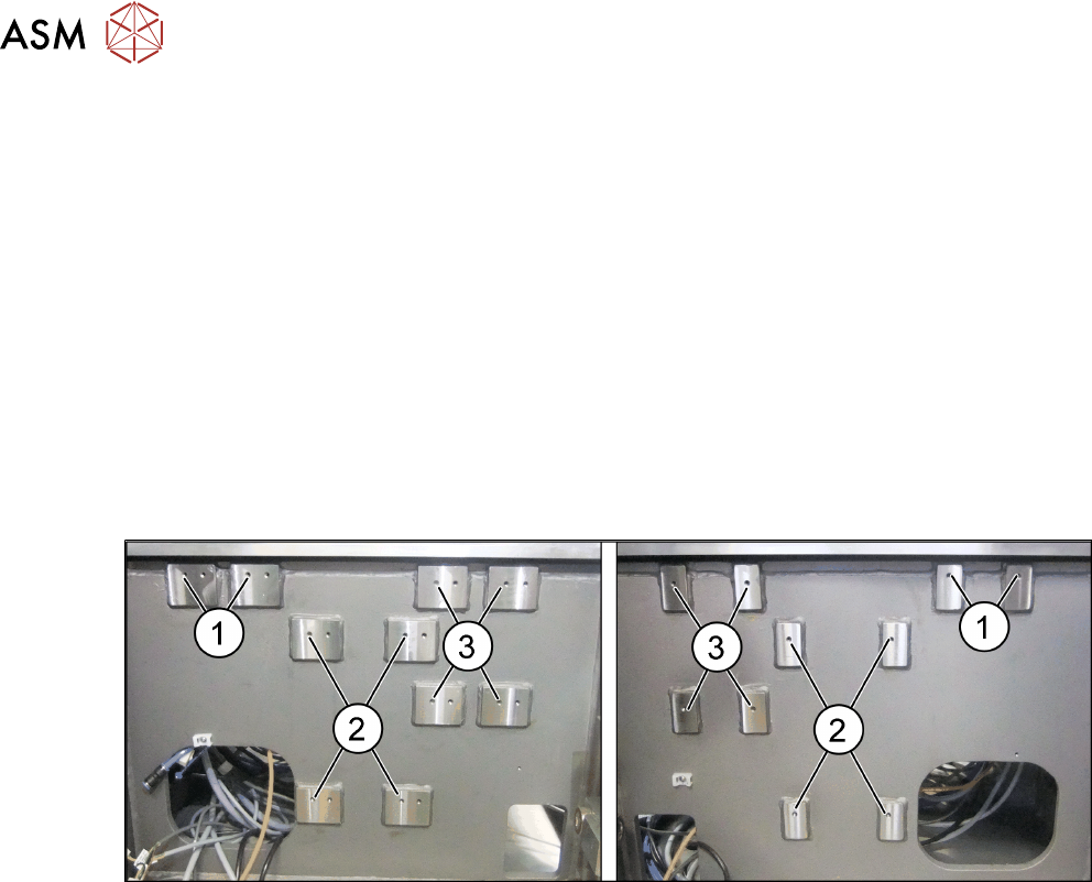
Screw fixing points at location 2 and 3
Fig.8: Screw fixing points at location 3 (left) and 2 (right)
1. Screw fixing points for the reject bin
2. Screw fixing points for the IC camera type 33
3. Screw fixing points for the IFC camera type 25
The screw fixing points at location 2 and 3 are mirrored. Use the left holes at location 2.
3 Installation
3.2 Fitting the Camera
Assembly Instructions / Montageanleitung SIPLACE X-Series S Stationary Camera Type 25/33 Stationäre Kamera
Typ 25/33 06/2016
89
Spacer plates for locations 2 and 3
Distance plate
Narrow spacer plates for locations 2 and 3
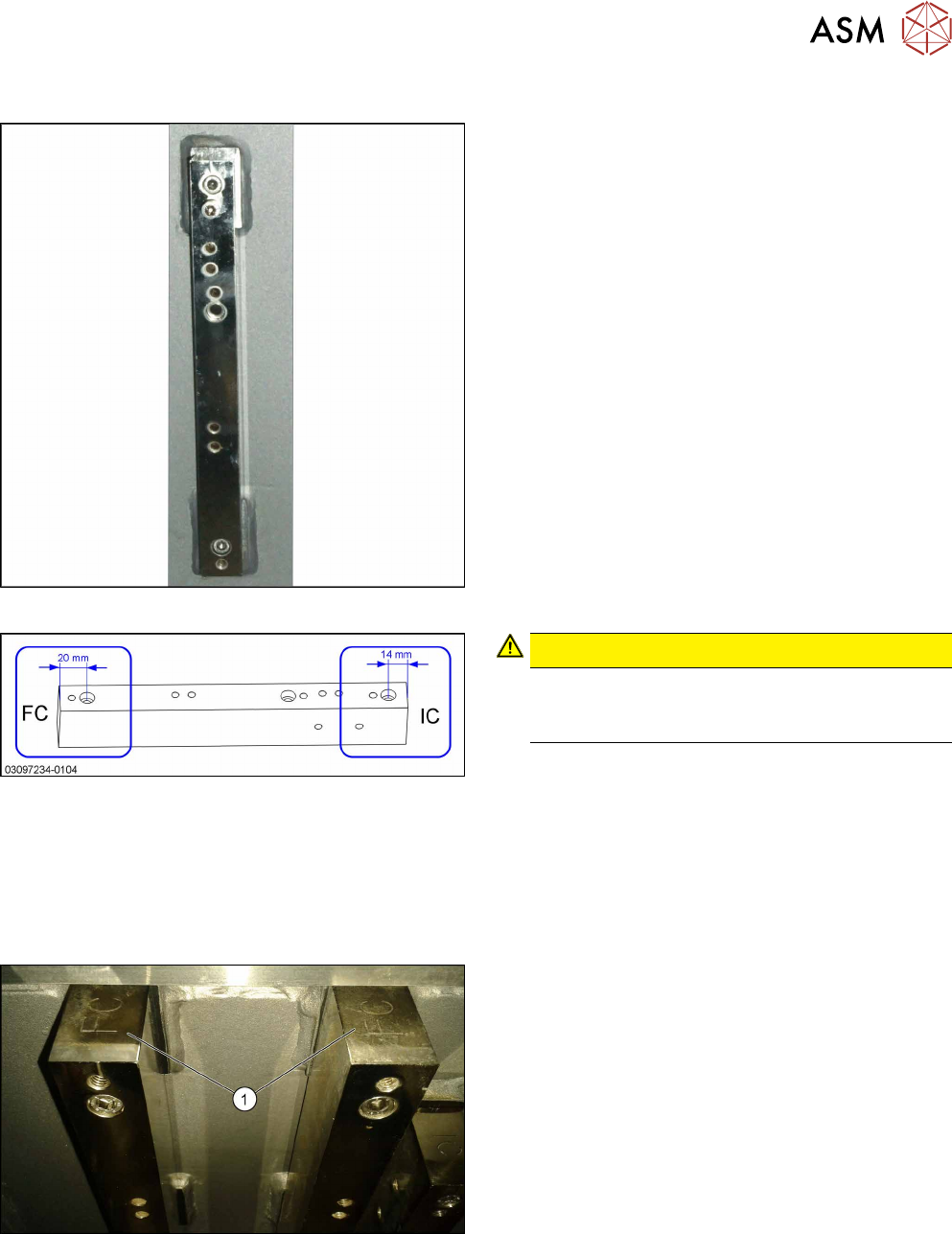
Correct labeling of spacer plates
CAUTION!
Incorrect labeling
In a few cases, these spacer plates are supplied
with incorrect labeling.
.
► Compare your spacer plates with the diagram.
If the label does not match the diagram, correct
the label.
●
– FC: This side must be on top for FC cameras
and Q10 magazines (Smart Pin Support).
– IC: This side must be on top for IC cameras.
Fitting the spacer plates
FC top
IC and FC are marked on the top and bottom of the
spacer plates.
When fitting an FC camera, make sure that the FC let-
tering (1) faces upwards.