00197397-02_AI_Stationary_Camera_25_33_X-Serie-S_to_Gxxxx_DE_EN.pdf - 第75页
3 Installation 3.1 Performing Preparatory Work Assembly Instructions / Montageanleitung SIPLACE X-Series S Stationary Camera Type 25/33 Stationäre Kamera Typ 25/33 06/2016 75 Fixture points for protective plate ► Hook th…
3 Installation
3.1 Performing Preparatory Work
74 Assembly Instructions / Montageanleitung SIPLACE X-Series S Stationary Camera Type 25/33 Stationäre Kamera
Typ 25/33 06/2016
3.1.1 Type X4i S Machines
The conversion work to an X4i S is only required if the table is in position 1 at the locations at which
the stationary cameras are to be fitted.
NOTICE
Positions occupied
It is not possible to occupy position 1 on one side and position 2 on the other side of the
same PA.
If the tables in PA1 are in position 2, the tables in PA2 must also be in position 2.
The configuration of tables in PA1 at position 1 and tables in PA2 at position 2 is also pos-
sible.
3.1.1.1 Adjusting the Hood
Before the COT insert can be moved to position 2, you need to replace the original protective cover
at the relevant location with the "protective sheet assembly" [03085665‑xx].
Parts required from "protective sheet assembly SX4/DX4" [03085665‑xx]
Quantity Designation Item number
1 Protective plate 03081408-xx
1 Track ruler and safety marking 03092020-xx
Conversion
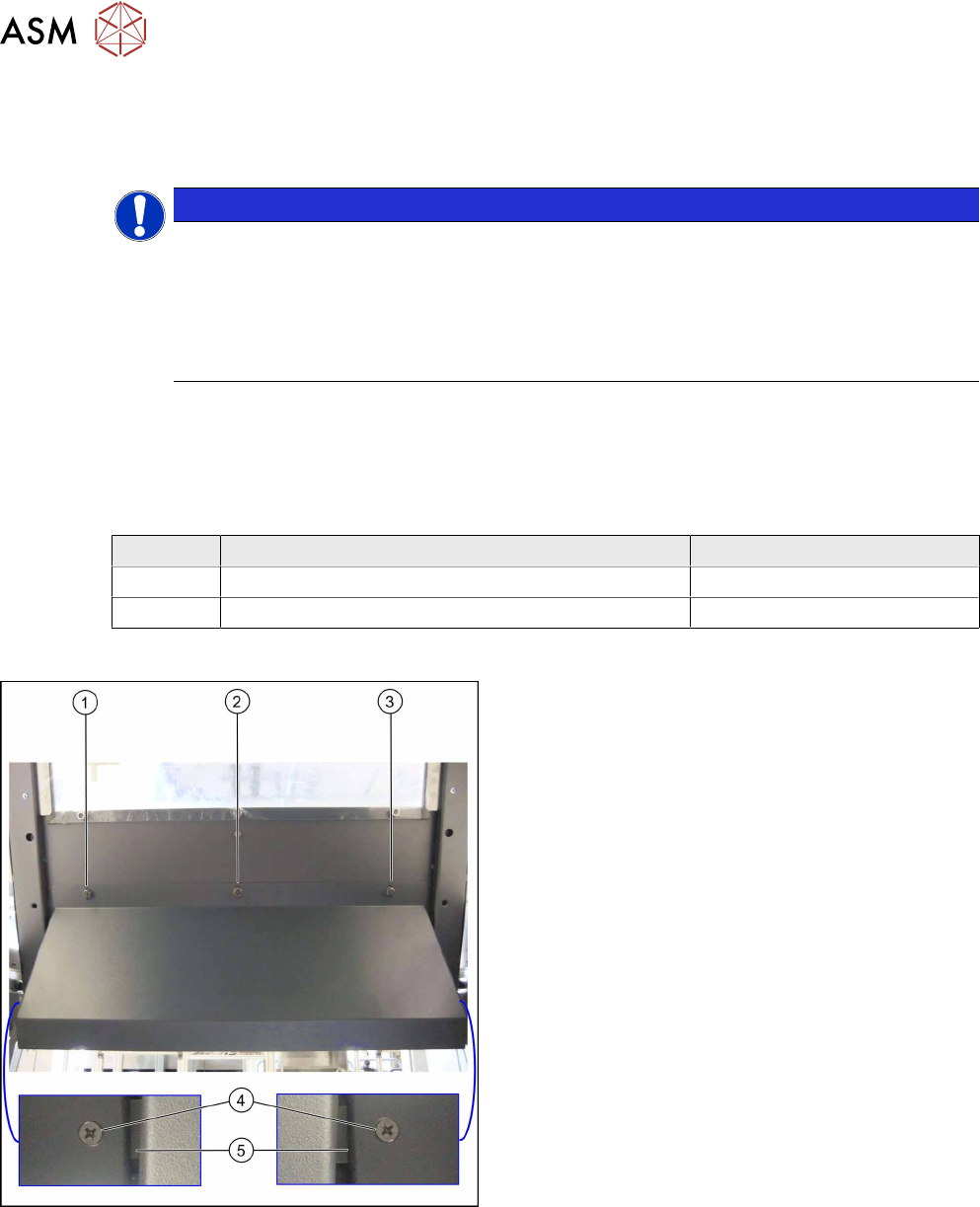
Hood with original protective cover at table position 1
There are three bolts on the inside of the cover (1) to
(3), where the protective cover is hooked up and fixed.
► Remove the three hexagonal nuts that fix the pro-
tective cover and lift off the original cover.
► At (4), remove the fixture plate on both sides (5).
3 Installation
3.1 Performing Preparatory Work
Assembly Instructions / Montageanleitung SIPLACE X-Series S Stationary Camera Type 25/33 Stationäre Kamera
Typ 25/33 06/2016
75
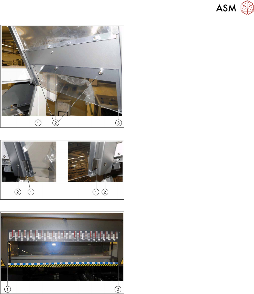
Fixture points for protective plate
► Hook the protective plate onto the three bolts and
fasten these into place with the three washers
and the hexagonal nuts (2) that you previously
removed.
► Also secure the protective plate with the fixture
plates on the left (1) and right (3).
Screwing the fixture plates into place
► Insert the fixture plates on the left and right (1).
► Screw the fixture plates (2) into place with the
screws that you previously removed.
Track ruler
The track ruler must be flat against the disk on the left
of all locations (1).
► Use adhesive to fix the track ruler at all locations
towards the machine center (2).
3 Installation
3.1 Performing Preparatory Work
76 Assembly Instructions / Montageanleitung SIPLACE X-Series S Stationary Camera Type 25/33 Stationäre Kamera
Typ 25/33 06/2016
3.1.1.2 Adjusting the Y Buffer
Before the COT insert can be moved to position 2, you need to shorten the length of the Y buffer at
the relevant location.
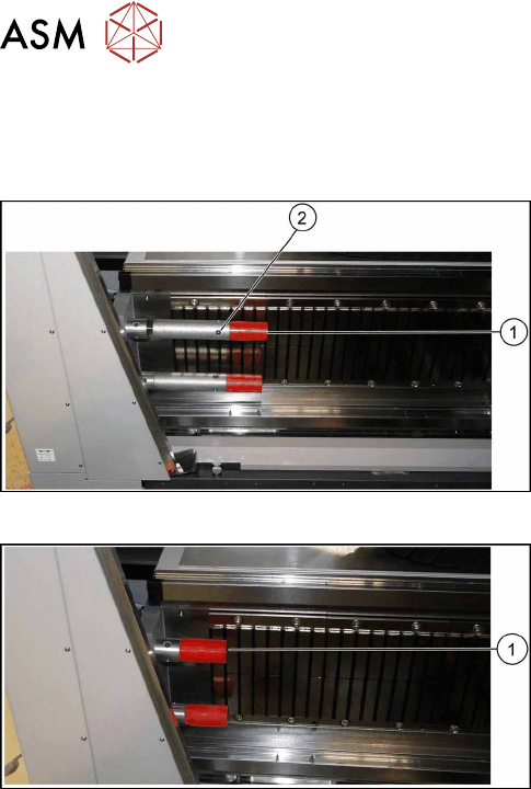
Length of Y buffer at table position 1
► Unscrew the top red buffer with the help of an
Allen key (1). Pay attention to the bushing.
► Insert the Allen key into one of the auxiliary holes
(2) and remove the middle section of the buffer.
► Repeat these steps for the lower buffer.
Length of Y buffer at table position 2
► Reinsert the red buffer and screw it tight (1).