00197397-02_AI_Stationary_Camera_25_33_X-Serie-S_to_Gxxxx_DE_EN.pdf - 第78页
3 Installation 3.1 Performing Preparatory Work 78 Assembly Instructions / Montageanleitung SIPLACE X-Series S Stationary Camera Type 25/33 Stationäre Kamera Typ 25/33 06/2016 3.1.1.4 Moving the COT Insert Outwards Locati…
3 Installation
3.1 Performing Preparatory Work
Assembly Instructions / Montageanleitung SIPLACE X-Series S Stationary Camera Type 25/33 Stationäre Kamera
Typ 25/33 06/2016
77
3.1.1.3 Adjusting the Hand Guard
Before the COT insert can be moved to position 2, you need to replace the original hand guard at
the relevant location with the shorter cover on the left and right.
Parts required
Quantity Designation Item number
1 Short cover, right on location 1 and 3 03086067-xx
1 Short cover, left on location 2 and 4 03086070-xx
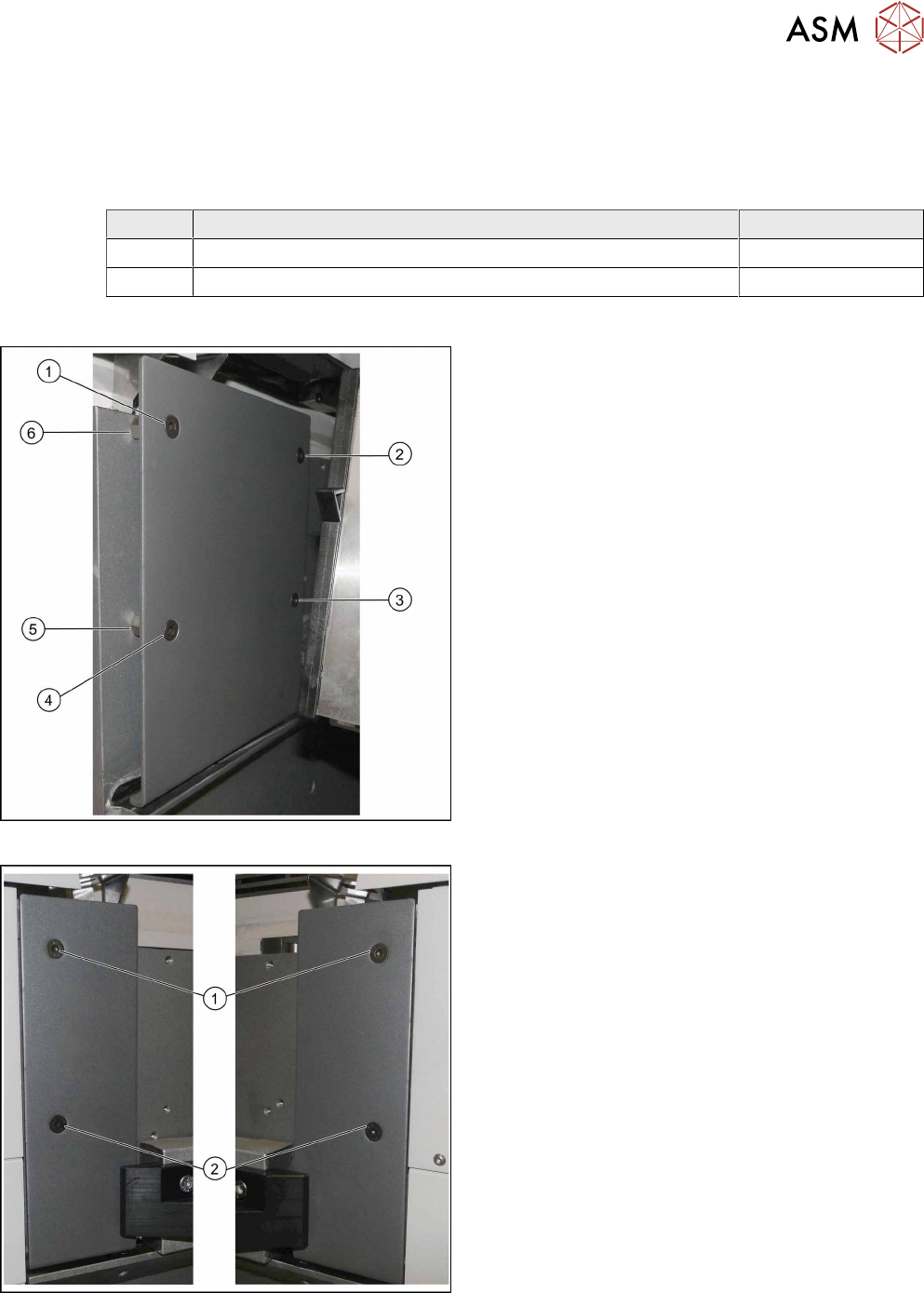
Conversion
Hand guard on left at table position 1
► Remove the screws at (1) to (4).
► Remove the spacer bolts underneath points (2)
and (3).
The two spacer bolts at (5) and (6) remain.
Short covers on left and right at table position 2
► Insert the short cover:
ð Short cover, right on location 1 and 3
ð Short cover, left on location 2 and 4
► Use the spacer bolts to screw the cover into
place at (1) and (2).
3 Installation
3.1 Performing Preparatory Work
78 Assembly Instructions / Montageanleitung SIPLACE X-Series S Stationary Camera Type 25/33 Stationäre Kamera
Typ 25/33 06/2016
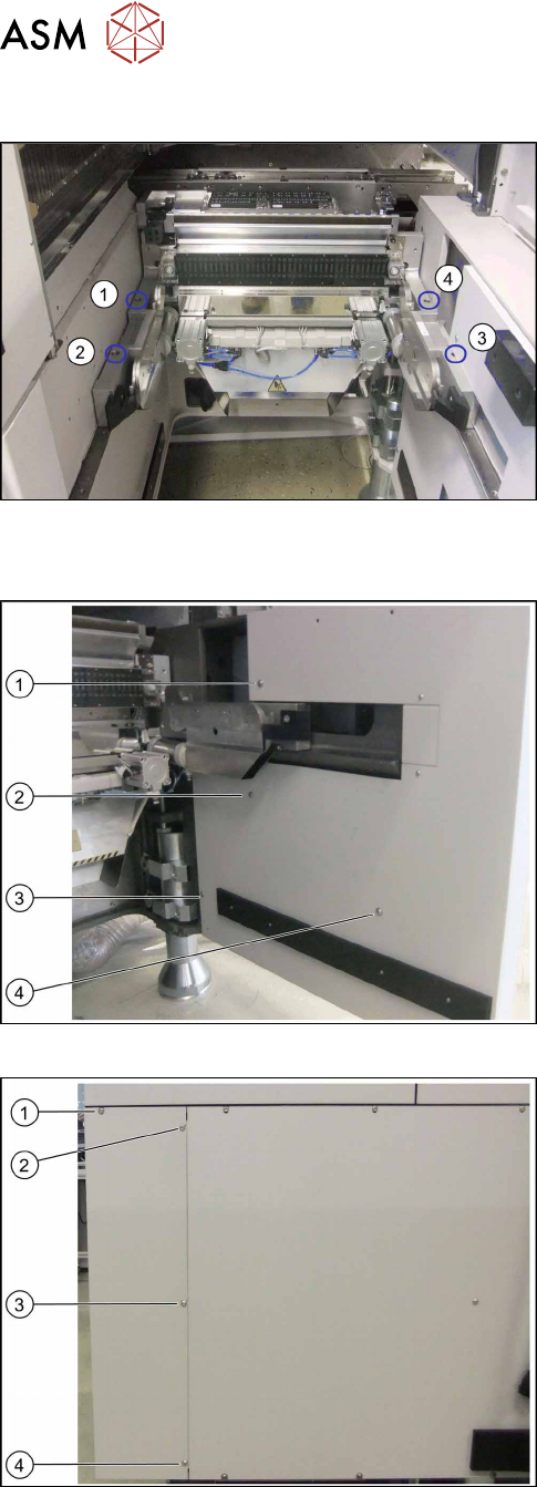
3.1.1.4 Moving the COT Insert Outwards
Location 4 on the X4i S – at first table position
(1) to (4): Positions of screws fastening the COT insert
To gain access to the screw at (3), you need to re-
move the outer side cover.
See also: 4.4.1 "Installation Positions of COT Insert
and Manual Table (Table Positions)" [}107]
Removing the side cover
Location 4 on X4i S – inner side cover
(1) to (3): Positions of fastening screws
► Remove the screws at (1) to (4).
Location 4 on X4i S – outer side cover
(1) to (4): Positions of fastening screws
► Remove the screw at (1).
► Loosen the screws at (2) to (4).
► Remove the side cover.
3 Installation
3.1 Performing Preparatory Work
Assembly Instructions / Montageanleitung SIPLACE X-Series S Stationary Camera Type 25/33 Stationäre Kamera
Typ 25/33 06/2016
79
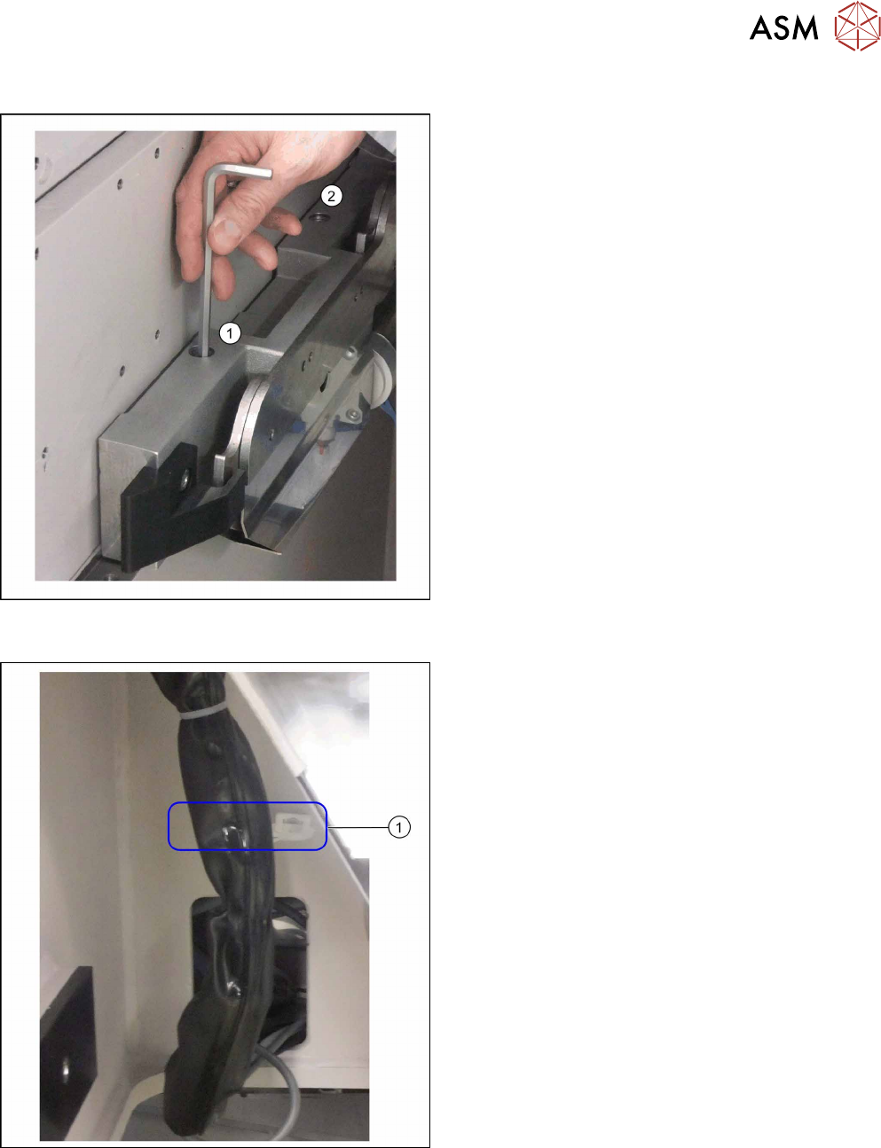
Moving the COT insert
(1) and (2) Fastening screws on the left of the COT in-
sert
► Remove the two fastening screws on both the left
and the right of the COT insert using an Allen key
or a T-handle.
Fixture point on machine frame
► Remove the cable ties at (1).