00197397-02_AI_Stationary_Camera_25_33_X-Serie-S_to_Gxxxx_DE_EN.pdf - 第74页
3 Installation 3.1 Performing Preparatory Work 74 Assembly Instructions / Montageanleitung SIPLACE X-Series S Stationary Camera Type 25/33 Stationäre Kamera Typ 25/33 06/2016 3.1.1 Type X4i S Machines The conversion work…

3 Installation
3.1 Performing Preparatory Work
Assembly Instructions / Montageanleitung SIPLACE X-Series S Stationary Camera Type 25/33 Stationäre Kamera
Typ 25/33 06/2016
73
3 Installation
NOTICE
Assembly Differences
The stationary cameras of type 33 (IC camera) and type 25 (FC camera) can be installed in
all X-Series S machine types. The design and assembly of the individual machine types is
the same in principle. Any relevant differences will be mentioned explicitly.
► Machines up to serial number Gxxxx accommodate stationary cameras with a hotlink
interface (without GigE).
Please read the assembly instructions "SIPLACE X-Series S – Stationary Camera
Type 25/33" [00197397‑xx].
► Machines from serial number Hxxxx accommodate stationary cameras with GigE.
Please read the assembly instructions "SIPLACE X-Series S – Stationary Camera
Type 25/33 (GigE)" [00197710‑xx].
CAUTION
Do not hold or carry the camera by its electronics unit.
The camera electronics assembly is a sensitive unit and can be easily damaged.
► Only hold or carry the camera by its metal frame.
► Always pull the illumination unit carefully up and off.
► The metal housing must always be hooked out of the lower section of the camera.
CAUTION
Crash danger
When fitting the camera, make sure that you observe the correct installation height, other-
wise this could create a risk of head crash.
3.1 Performing Preparatory Work
► If necessary: use the software to move the conveyor sides into the position which allows you
best access. Alternatively, you can also loosen the conveyor side clamps on the dual con-
veyor (see service manual).
► Switch off the machine, disconnect it from the power supply and secure it to prevent unauthor-
ized reactivation. Observe the instructions in section 1.2 "Preparatory Work..." [}63].
► Dismantle the waste tape chute.
► If you need to install a "row 2" nozzle changer (machine types X3 S and X4 S), read the
assembly instructions for "Row 2 Nozzle Changer – Nozzle Change Before
MTC" [00197369-xx].
► Perform the additional conversion work to machines of type X4i S (see 3.1.1 "Type X4i S Ma-
chines" [}74]).
► For machines of types X3 S and X4 S, continue with section 3.2 "Fitting the Camera" [}81].
3 Installation
3.1 Performing Preparatory Work
74 Assembly Instructions / Montageanleitung SIPLACE X-Series S Stationary Camera Type 25/33 Stationäre Kamera
Typ 25/33 06/2016
3.1.1 Type X4i S Machines
The conversion work to an X4i S is only required if the table is in position 1 at the locations at which
the stationary cameras are to be fitted.
NOTICE
Positions occupied
It is not possible to occupy position 1 on one side and position 2 on the other side of the
same PA.
If the tables in PA1 are in position 2, the tables in PA2 must also be in position 2.
The configuration of tables in PA1 at position 1 and tables in PA2 at position 2 is also pos-
sible.
3.1.1.1 Adjusting the Hood
Before the COT insert can be moved to position 2, you need to replace the original protective cover
at the relevant location with the "protective sheet assembly" [03085665‑xx].
Parts required from "protective sheet assembly SX4/DX4" [03085665‑xx]
Quantity Designation Item number
1 Protective plate 03081408-xx
1 Track ruler and safety marking 03092020-xx
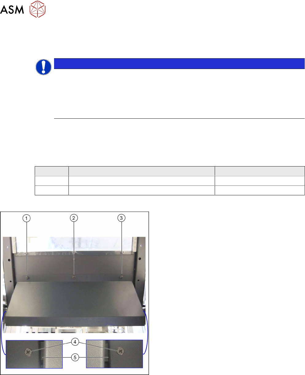
Conversion
Hood with original protective cover at table position 1
There are three bolts on the inside of the cover (1) to
(3), where the protective cover is hooked up and fixed.
► Remove the three hexagonal nuts that fix the pro-
tective cover and lift off the original cover.
► At (4), remove the fixture plate on both sides (5).
3 Installation
3.1 Performing Preparatory Work
Assembly Instructions / Montageanleitung SIPLACE X-Series S Stationary Camera Type 25/33 Stationäre Kamera
Typ 25/33 06/2016
75
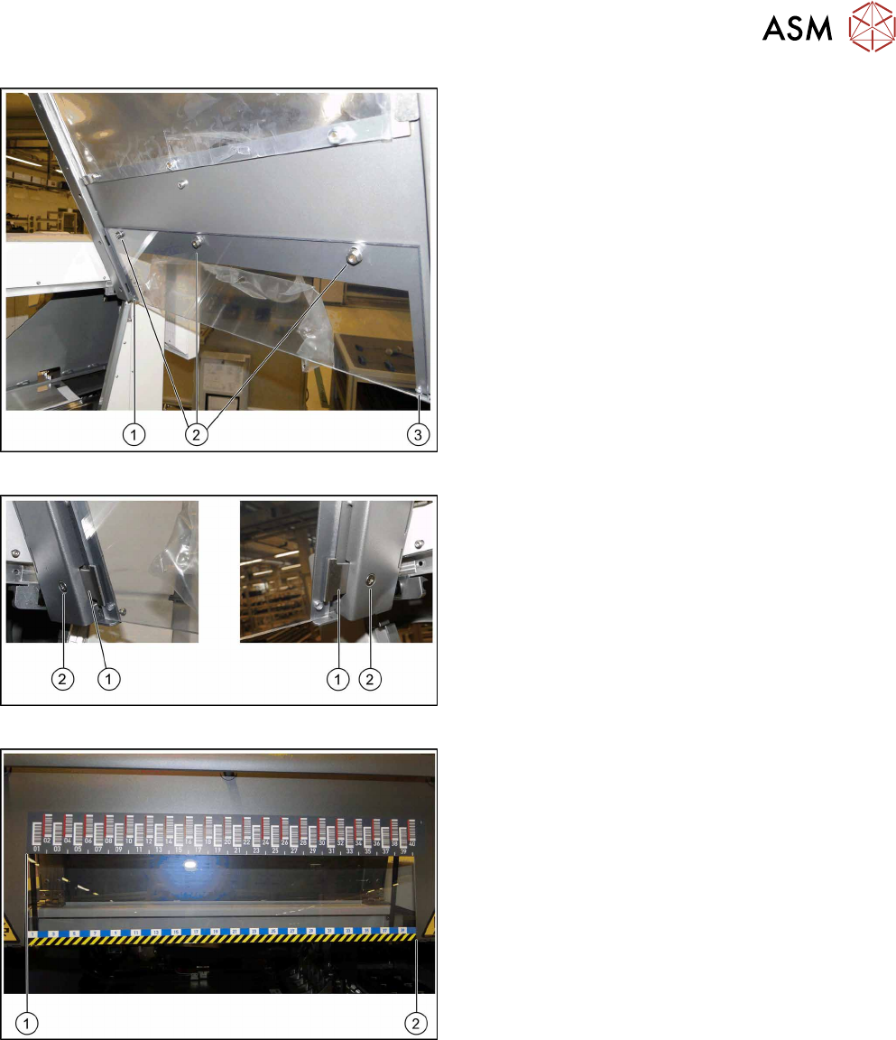
Fixture points for protective plate
► Hook the protective plate onto the three bolts and
fasten these into place with the three washers
and the hexagonal nuts (2) that you previously
removed.
► Also secure the protective plate with the fixture
plates on the left (1) and right (3).
Screwing the fixture plates into place
► Insert the fixture plates on the left and right (1).
► Screw the fixture plates (2) into place with the
screws that you previously removed.
Track ruler
The track ruler must be flat against the disk on the left
of all locations (1).
► Use adhesive to fix the track ruler at all locations
towards the machine center (2).