00197397-02_AI_Stationary_Camera_25_33_X-Serie-S_to_Gxxxx_DE_EN.pdf - 第106页
4 Appendix 4.3 Circuit Diagrams 106 Assembly Instructions / Montageanleitung SIPLACE X-Series S Stationary Camera Type 25/33 Stationäre Kamera Typ 25/33 06/2016 4.3 Circuit Diagrams For more information, refer to the cir…
4 Appendix
4.1 Installation Height of the Stationary Camera
Assembly Instructions / Montageanleitung SIPLACE X-Series S Stationary Camera Type 25/33 Stationäre Kamera
Typ 25/33 06/2016
105
4 Appendix
4.1 Installation Height of the Stationary Camera
CAUTION
Observe the installation height
When fitting the camera, observe the correct installation height "I". Otherwise there is a risk
of head crash!
► When setting the installation height, consider all the heads in one placement area.
► If you are using a stationary camera with a CPP head, the CPP head must be fitted in
the top position.
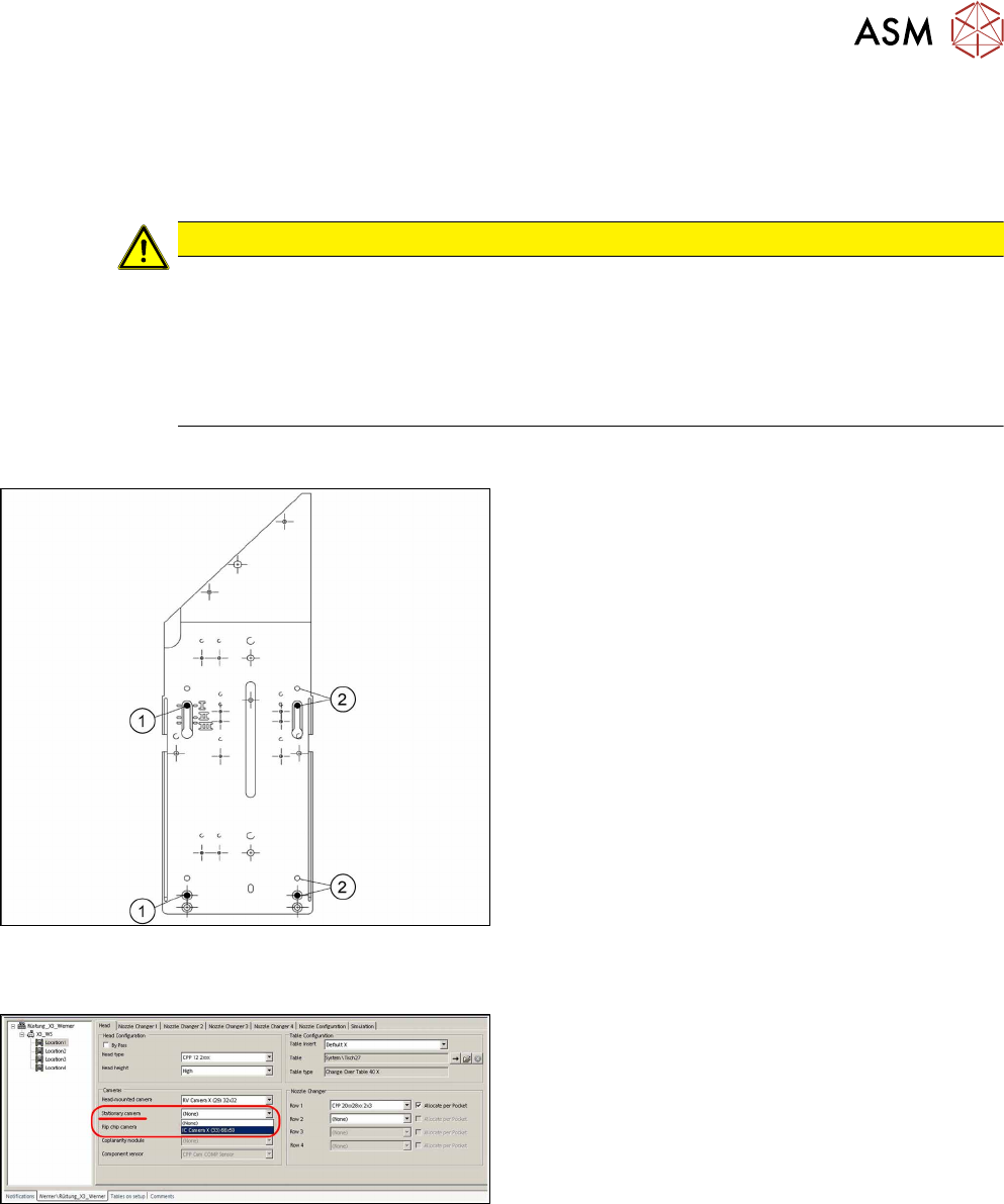
4.1.1 Stationary Camera in Position 1
If you are using a DLM or CPP head in a placement
area, fit the camera in the bottom position. This
equates to position I.
1. Screw
2. Thread in the machine frame
Position I has to be used in the following cases:
●
X series S: always
4.2 Configuration of Stationary Camera with SIPLACE PRO
Configuration of stationary camera (SIPLACE Pro
setup (shown using example ofX3)
► Select Setup → Location → Head tab and enter
the P&P head.
► Re-optimize the setup in SIPLACE Pro.
4 Appendix
4.3 Circuit Diagrams
106 Assembly Instructions / Montageanleitung SIPLACE X-Series S Stationary Camera Type 25/33 Stationäre Kamera
Typ 25/33 06/2016
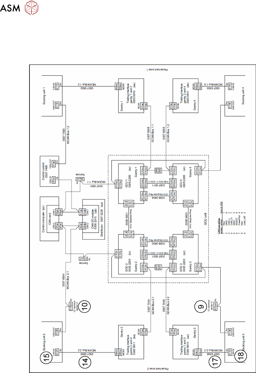
4.3 Circuit Diagrams
For more information, refer to the circuit diagrams folder:
●
Circuit diagram folder SIPLACE X-Series S (up to Gxxxx) [00197021‑xx]
4.3.1 Camera CAN bus
Fig.11: Camera CAN bus
4 Appendix
4.4 Excerpts from the Service Manual
Assembly Instructions / Montageanleitung SIPLACE X-Series S Stationary Camera Type 25/33 Stationäre Kamera
Typ 25/33 06/2016
107
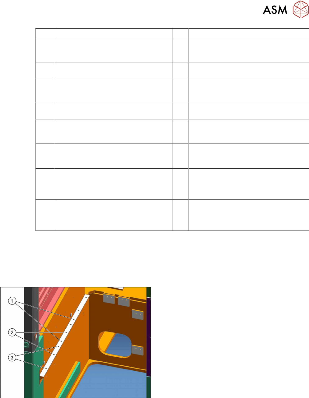
1 IC camera 2 FC camera
3 Camera bus cable IC/FC camera
[03077048-xx] location 2 to hotlink card
Cam 2 (X2) control computer
4 Camera bus cable IC/FC camera
[03077049-xx] location 3 to hotlink card
Cam 3 (X3) control computer
5 Hotlink card control computer 6 Cable IC/FC camera voltages [03076478-
W1] location 2 to subdistributor X7qa
7 Cable IC/FC camera voltages
[03076478-W2] location 3 to subdistrib-
utor X7qa
8 Subdistributor X7qa voltage stationary
camera
9 CAN bus X10cm sector 3 (only for direct
connection of IC camera)
10 CAN bus X10bm sector 2 (only for direct
connection of IC camera)
11 Cable extension camera bus IC/FC cam-
era [03055279-xx]. Only for IC and FC
camera at one location
12 Cable extension camera bus IC/FC cam-
era [03055279-xx]. Only for IC and FC
camera at one location
13 Cable: Extension power FC camera
[03055298-xx]. Only for IC and FC cam-
era at one location
14 Cable MCAN-Bus2.2 [03076505-xx] from
docking unit 2 X125So. Only for IC and
FC camera at location 2
15 Connector X125 CAN in on COT insert
[03076504-xx] from docking unit 2
X125So. Only for IC and FC camera at
location 2
16 CAN bus: IC and FC camera
[03050550-xx]. Only for IC and FC cam-
era at one location
17 Cable: MCAN-Bus2.3 [03076506-xx]
from docking unit 3 X135So. Only for IC
and FC camera at location 3
18 Connector X135 CAN in on COT insert
[03076504-xx] from docking unit 3
X135So. Only for IC and FC camera at
location 3
4.4 Excerpts from the Service Manual
The following chapters are excerpts from the service manual. For more information, refer to the full
service manual for your machine.
4.4.1 Installation Positions of COT Insert and Manual Table (Table Positions)
The following installation positions apply to the X
series S:
1. Installation position 1
COT insert: X4i S
2. Installation position 2
COT insert, manual table: X4i S
3. Installation position 3
COT insert, manual table: X2 S, X3 S, X4 S