00197397-02_AI_Stationary_Camera_25_33_X-Serie-S_to_Gxxxx_DE_EN.pdf - 第69页
2 Brief Description 2.1 Product Description Assembly Instructions / Montageanleitung SIPLACE X-Series S Stationary Camera Type 25/33 Stationäre Kamera Typ 25/33 06/2016 69 2 Brief Description 2.1 Product Description X-Se…

1 Introduction
1.4 Staff Qualifications and Training
68 Assembly Instructions / Montageanleitung SIPLACE X-Series S Stationary Camera Type 25/33 Stationäre Kamera
Typ 25/33 06/2016
1.4 Staff Qualifications and Training
Qualified or adequately trained personnel means that these people are familiar with the setting up,
operation and maintenance of the machine and the add-on devices and are suitably qualified, e.g.:
●
Have been trained, instructed or authorized to switch on and off, isolate, earth and identify
electrical circuits and system components in accordance with normal safety standards.
●
Have been trained or instructed in the upkeep and use of appropriate safety equipment in
accordance with normal safety standards.
●
Have received first aid training.
2 Brief Description
2.1 Product Description
Assembly Instructions / Montageanleitung SIPLACE X-Series S Stationary Camera Type 25/33 Stationäre Kamera
Typ 25/33 06/2016
69
2 Brief Description
2.1 Product Description
X-Series S machines with machine numbers up to Gxxxx can optionally accommodate one or two
stationary cameras "IC camera type 33" or "FC camera type 25". Only stationary cameras without
GigE can be used.
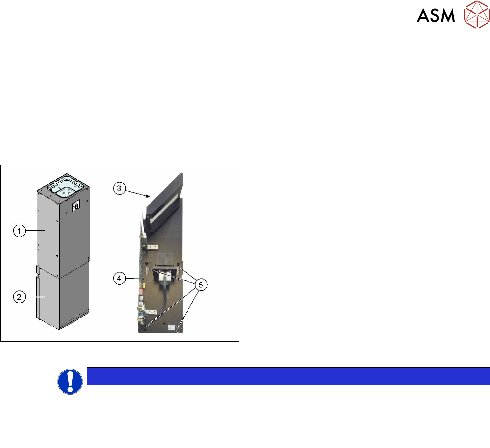
Camera design
Example of type 33 shown
Stationary camera design
1. Upper section of camera (illumination unit)
2. Lower section of camera
3. Mirror
4. Camera electronics
5. Holes for fastening screws
NOTICE
The camera upper section has a fixed assignment to the camera lower section.
The camera upper section may not be used with another camera lower section. Both the
upper and lower sections are mechanically and electrically coordinated and may not be ex-
changed for use with other cameras. The serial and version numbers of the top and bottom
sections of the camera must be identical.
2 Brief Description
2.1 Product Description
70 Assembly Instructions / Montageanleitung SIPLACE X-Series S Stationary Camera Type 25/33 Stationäre Kamera
Typ 25/33 06/2016
2.1.1 Technical Data.
Component Camera, Stationary, P&P (Type 33) 55x45
Component dimensions 0.5 mm x 0.5 mm to 55 mm x 45 mm for single measurement of
component
Component spectrum 0402, MELF, SO, PLCC, QFP, electrolytic capacitors, BGA
Min. lead pitch 0.30 mm
Min. lead width 0.15 mm
Min. ball pitch 0.35 mm
Min. ball diameter 0.20 mm
Field of view 65 x 50 mm
2
Method of illumination Front-lighting (6 levels, programmable as required)
Stationary P&P component camera (type 25) 16 x 16, digital (FC camera)
Component dimensions 0.2 mm x 0.2 mm to 16 mm x 16 mm for single measurement of
component
Component spectrum 0402 to SO, PLCC, QFP, sockets, plugs, BGA, special components,
bare dies, flip-chips, shields
Min. lead pitch 0.25 mm
Min. lead width 0.1 mm
Min. ball pitch 0.14 mm
Min. ball diameter 0.08 mm
Field of view 19.4 x 19.4 mm
Method of illumination Front-lighting (6 levels, programmable as required)
2.1.2 Version Overview
Version
SST33
Description
01, 02 Not available for these machines
03 to 06 With CAN controller (as TQ module), VCU not required, 8 pin DIP switch on the driver
board
From 06 Simpler assembly with key holes
From 07 With CAN controller (integrated on the board), VCU not required, 6 pin DIP switch on
the driver board
Version
SST25
Description
01 Not available for these machines
From 03 Depending on the type series, the camera either has an 8 pin or 6 pin DIP switch in it.
The CAN controller is located directly on the driver board.
From 05 With CAN controller (integrated on the board), VCU not required. Version 03 and 05
have the same design. Multiplexer integrated on the board.