00197397-02_AI_Stationary_Camera_25_33_X-Serie-S_to_Gxxxx_DE_EN.pdf - 第56页
4 Anhang 4.4 Auszüge aus der Serviceanleitung 56 Assembly Instructions / Montageanleitung SIPLACE X-Series S Stationary Camera Type 25/33 Stationäre Kamera Typ 25/33 06/2016 4.4.2 Übersicht Anschlüsse BoxPC 627x/827x 4.4…
4 Anhang
4.4 Auszüge aus der Serviceanleitung
Assembly Instructions / Montageanleitung SIPLACE X-Series S Stationary Camera Type 25/33 Stationäre Kamera
Typ 25/33 06/2016
55
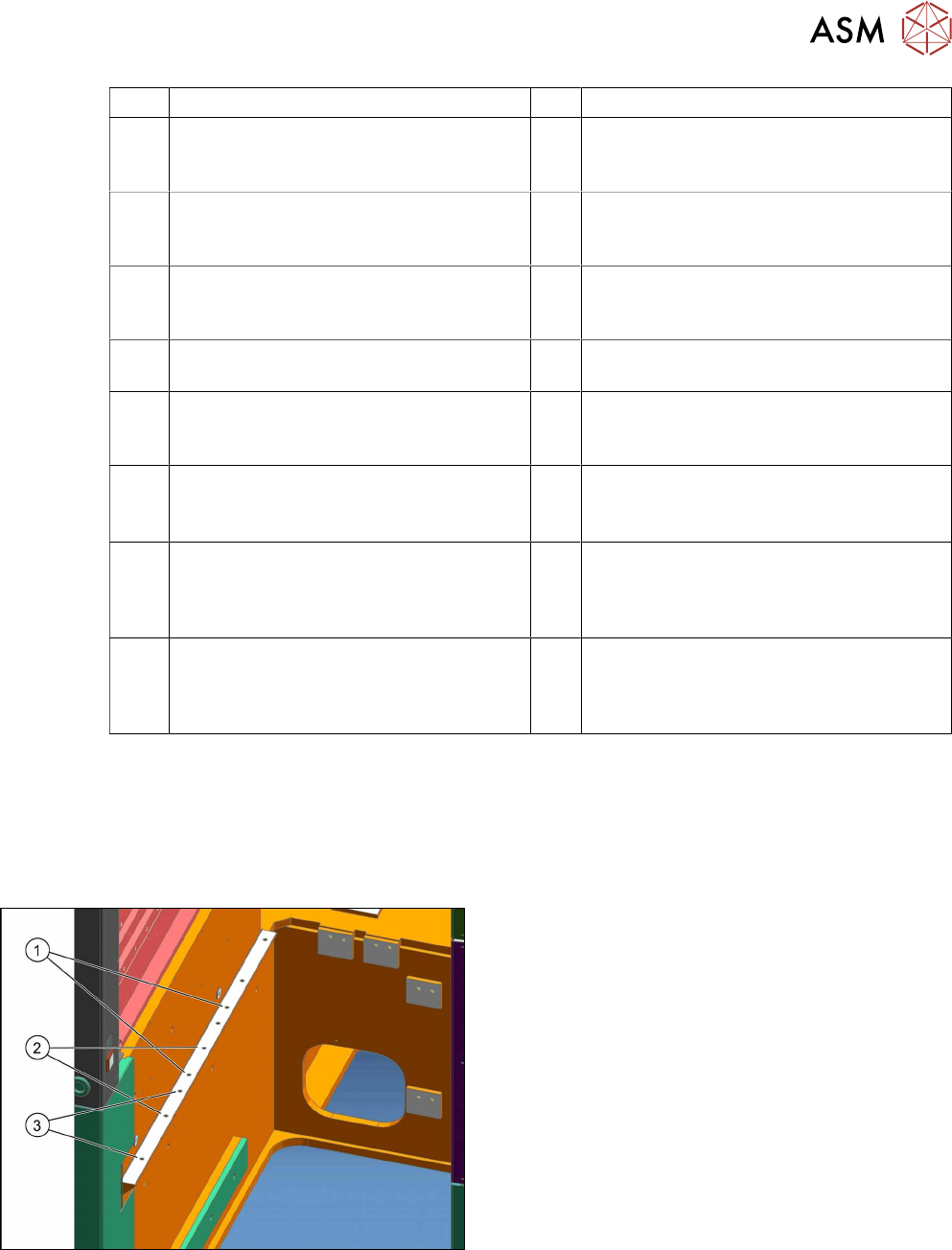
1 IC-Kamera 2 FC-Kamera
3 Kamerabus Kabel IC/FC-Kamera
[03077048-xx] Stellplatz 2 zur Hotlinkkar-
te Cam 2 (X2) Steuerrechner
4 Kamerabus Kabel IC/FC-Kamera
[03077049-xx] Stellplatz 3 zur Hotlinkkarte
Cam 3 (X3) Steuerrechner
5 Hotlinkkarte Steuerrechner 6 Kabel Spannungen IC/FC-Kamera
[03076478-W1] Stellplatz 2 zum Unterver-
teiler X7qa
7 Kabel Spannungen IC/FC-Kamera
[03076478-W2] Stellplatz 3 zum Unter-
verteiler X7qa
8 Unterverteiler X7qa Spannung stationäre
Kameras
9 CAN-Bus X10cm Sektor 3 (nur bei direk-
tem Anschluss der IC-Kamera)
10 CAN-Bus X10bm Sektor 2 (nur bei direk-
tem Anschluss der IC-Kamera)
11 Kabel Verlängerung Kamerabus IC/FC-
Kamera [03055279-xx]. Nur bei IC- und
FC-Kamera an einem Stellplatz
12 Kabel Verlängerung Kamerabus IC/FC-
Kamera [03055279-xx]. Nur bei IC- und
FC-Kamera an einem Stellplatz
13 Kabel Verlängerung Power FC-Kamera
[03055298-xx]. Nur bei IC- und FC-
Kamera an einem Stellplatz
14 Kabel MCAN-Bus2.2 [03076505-xx] von
Docking-Unit 2 X125So. Nur bei IC- und
FC-Kamera am Stellplatz 2
15 Stecker X125 CAN in am BE-Einzug
[03076504-xx] von Docking-Unit 2 X125-
So. Nur bei IC- und FC-Kamera am Stell-
platz 2
16 CAN-Bus: IC- und FC-Kamera
[03050550-xx]. Nur bei IC- und FC-
Kamera an einem Stellplatz
17 Kabel: MCAN-Bus2.3 [03076506-xx] von
Docking-Unit 3 X135So. Nur bei IC- und
FC-Kamera am Stellplatz 3
18 Stecker X135 CAN in am BE-Einzug
[03076504-xx] von Docking-Unit 3 X135-
So. Nur bei IC- und FC-Kamera am Stell-
platz 3
4.4 Auszüge aus der Serviceanleitung
Die folgenden Kapitel sind Auszüge aus der Serviceanleitung. In der Serviceanleitung Ihrer
Maschine finden Sie ggf. weitere Informationen.
4.4.1 Einbaupositionen BE-Einzug und manueller Tisch (Tischpositionen)
An der X-Serie S gibt es folgende Einbaupositionen:
1. Einbauposition 1
BE-Einzug: X4i S
2. Einbauposition 2
BE-Einzug, manueller Tisch: X4i S
3. Einbauposition 3
BE-Einzug, manueller Tisch: X2 S, X3 S, X4 S
4 Anhang
4.4 Auszüge aus der Serviceanleitung
56 Assembly Instructions / Montageanleitung SIPLACE X-Series S Stationary Camera Type 25/33 Stationäre Kamera
Typ 25/33 06/2016
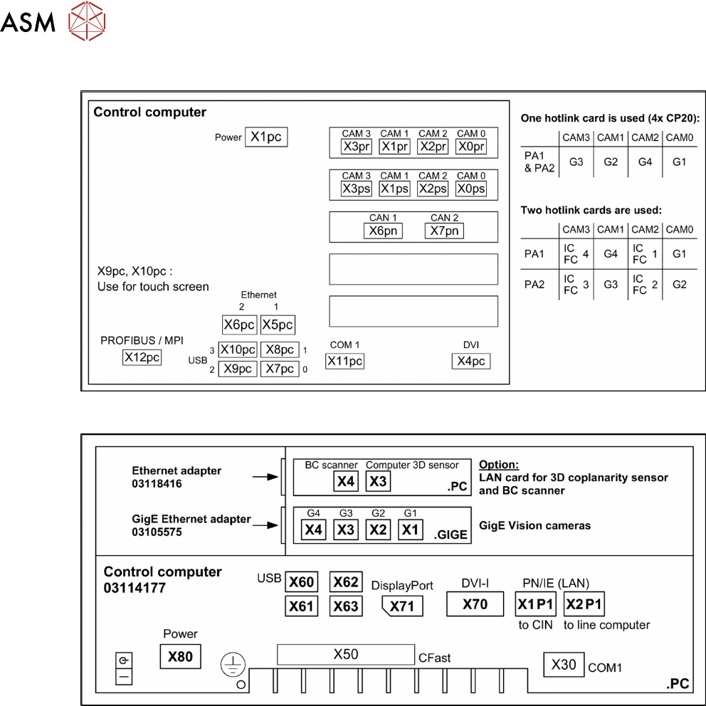
4.4.2 Übersicht Anschlüsse BoxPC 627x/827x
4.4.3 Übersicht Anschlüsse BoxPC 427D

57Assembly Instructions / Montageanleitung SIPLACE X-Series S Stationary Camera Type 25/33 Stationäre Kamera
Typ 25/33 06/2016
Table of Contents
Table of Contents
1 Introduction.. 59
1.1 Safety Instructions.. 59
1.1.1 Conventions for the use of safety instructions.. 59
1.1.2 Safety Instructions for Working with Strong Magnetic Fields.. 60
1.1.3 Safety Instructions for the Power Supply (Without SMPS).. 60
1.1.4 Safety instructions for the compressed air supply.. 61
1.1.5 Safety Instructions for Work on the Cutting Device.. 61
1.1.6 Safety Instructions for the Gantry.. 61
1.1.7 Safety Instructions on Hazardous Materials.. 62
1.1.8 Classification of the Optical Systems.. 62
1.1.8.1 Classification of the Whole Machine.. 62
1.1.8.2 Laser Classification.. 62
1.1.8.3 Classification of the Camera Systems.. 62
1.2 Preparatory Work..... 63
1.3 Other Instructions.. 66
1.3.1 Environmentally-Friendly Disposal of Materials and Components.. 66
1.3.2 Use of Original SIPLACE Accessories and Spare Parts.. 66
1.3.3 ESD Guidelines.. 66
1.3.3.1 Definition of ESD.. 66
1.3.3.2 Important Measures to Protect Against Static Charging.. 66
1.3.3.3 Handling ESD Modules.. 67
1.3.3.4 Measurements and Modifications to ESD Modules.. 67
1.3.3.5 Dispatching ESD Modules.. 67
1.3.4 Release History.. 67
1.4 Staff Qualifications and Training.. 68
2 Brief Description.. 69
2.1 Product Description.. 69
2.1.1 Technical Data... 70
2.1.2 Version Overview.. 70
2.2 Overview of X Series S Machines.. 71
2.3 Requirements.. 71
2.4 Configurations.. 71
2.5 Scope of Delivery.. 72
2.6 Tools and Equipment Required.. 72
2.7 Required Working Time.. 72
3 Installation.. 73
3.1 Performing Preparatory Work.. 73
3.1.1 Type X4i S Machines.. 74
3.1.1.1 Adjusting the Hood.. 74
3.1.1.2 Adjusting the Y Buffer.. 76
3.1.1.3 Adjusting the Hand Guard.. 77
3.1.1.4 Moving the COT Insert Outwards.. 78
3.2 Fitting the Camera.. 81
3.2.1 Adjusting the Camera Jumper Setting.. 82
3.2.1.1 Coding the DIP Switch (8 Pin).. 82
3.2.1.2 Coding the DIP Switch (6 Pin).. 83
3.2.2 Fitting the IC Camera Type 33.. 83