00197397-02_AI_Stationary_Camera_25_33_X-Serie-S_to_Gxxxx_DE_EN.pdf - 第85页
3 Installation 3.2 Fitting the Camera Assembly Instructions / Montageanleitung SIPLACE X-Series S Stationary Camera Type 25/33 Stationäre Kamera Typ 25/33 06/2016 85 Spacer plates for locations 2 and 3 Narrow spacer plat…
3 Installation
3.2 Fitting the Camera
84 Assembly Instructions / Montageanleitung SIPLACE X-Series S Stationary Camera Type 25/33 Stationäre Kamera
Typ 25/33 06/2016
3.2.2.1 Fitting the Spacer Plates
The spacer plates are fixed to the relevant screw fixing points in the machine base. Narrow spacer
plates are used at locations 2 and 3, while wide spacer plates are used at locations 1 and 4.
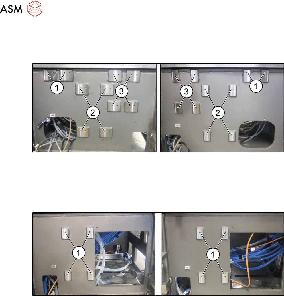
Screw fixing points at location 2 and 3
Fig.5: Screw fixing points at location 2 (left) and 3 (right)
1. Screw fixing points for the reject bin
2. Screw fixing points for the IC camera type 33
3. Screw fixing points for the IFC camera type 25
The screw fixing points at location 2 and 3 are mirrored. Use the left holes at location 2.
Screw fixing points at location 1 and 4
Fig.6: Screw fixing points at location 1 (left) and 4 (right)
1. Screw fixing points for the IC camera type 33
3 Installation
3.2 Fitting the Camera
Assembly Instructions / Montageanleitung SIPLACE X-Series S Stationary Camera Type 25/33 Stationäre Kamera
Typ 25/33 06/2016
85
Spacer plates for locations 2 and 3
Narrow spacer plates for locations 2 and 3
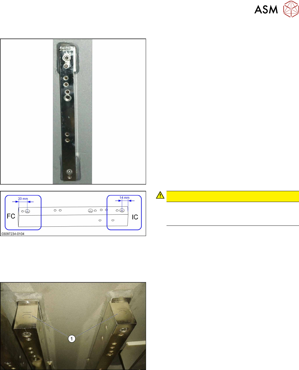
Correct labeling of spacer plates
CAUTION!
Incorrect labeling
In a few cases, these spacer plates are supplied
with incorrect labeling.
.
► Compare your spacer plates with the diagram.
If the label does not match the diagram, correct
the label.
●
– FC: This side must be on top for FC cameras
and Q10 magazines (Smart Pin Support).
– IC: This side must be on top for IC cameras.
IC top
IC and FC are marked on the top and bottom of the
spacer plates.
When fitting an IC camera, make sure that the IC let-
tering (1) faces upwards.
3 Installation
3.2 Fitting the Camera
86 Assembly Instructions / Montageanleitung SIPLACE X-Series S Stationary Camera Type 25/33 Stationäre Kamera
Typ 25/33 06/2016
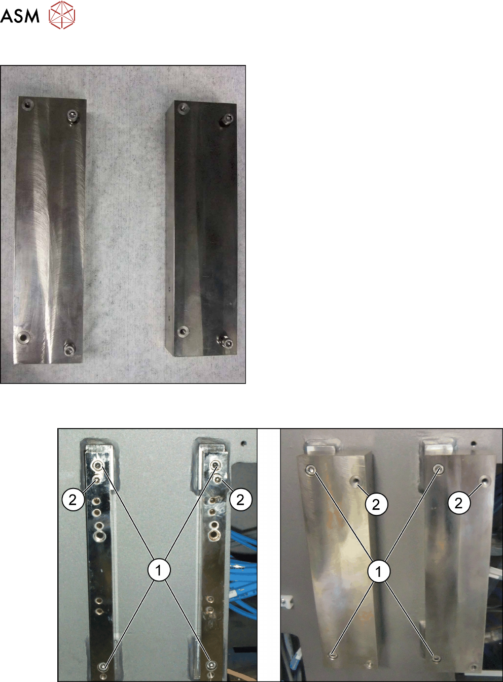
Spacer plates for locations 1 and 4
Spacer plates
Wide spacer plate for locations 1 and 4 with plug-in
screws for fixture to machine frame.
Fitting the spacer plates
Fig.7: Left: location 2 and 3; right: location 1 and 4
► Use the screws (M6x45) to fix the spacer plates to the screw fixing points in the machine
frame (1). Make sure that the IC label indicates upwards.
► At position (2), tighten the two screws M6x25 [03042575-xx] for the camera suspension
holder, until the screw shaft protrudes approx. 15mm above the mount.