2500_Users_Manual.pdf - 第102页
Task s and Ki ts ProM aster 25 00 User Manua l 3-27 Note: To enable printing a serial number on a label, e nter two or more consec utive pe rcen t signs ( %) in t he text field. You must ent er one perce nt sign fo r eac…

Tasks and Kits
3-26 ProMaster 2500 User Manual
The following example gives these sample values for the parameters: a
10-character ASCII hexadecimal serial number at address 12345
(hexadecimal), increase the serial number by an increment of 2 for each
device programmed, and print each serial number on the device label (in
hexadecimal). The Program entry field in the
Setup/Serialization
dialog
box might look like this:
serializ.exe
–l10 –fh –a12345 –i2 –h
Parameter Description
–a
Address of serial number.
Defines the device address (hexadecimal value) where the
serial number will be programmed in the device. For
example, –a12345 places the serial number at hexadecimal
address 12345.
Default
: Zero (–a0)
–f
Format of serial number.
Defines the format of the serial number in the device.
These three formats are supported:
–fb = Binary
–fd = ASCII decimal
–fh = ASCII hexadecimal
Default:
Binary (–fb)
–i
Serial number increment.
Defines the decimal value to be used to increment the
serial number after each successfully programmed
device. For example, –i2 increases the serial number by 2
for each device programmed.
Default:
1 (–i1)
-l
Length of serial number.
Defines the number of bytes the serial number occupies in
the device. The following settings are supported.
1 through 4 Binary
1 through 8 ASCII hexadecimal
1 through 10 ASCII decimal
Default:
2 (–l2)
–m
Pure Set gang serialization mode.
Serial numbers are generated one device size apart in
programmer RAM instead of in a single block just beyond
the fixed data in RAM. TaskLink then programs devices
in a single-pass operation with a set size equal to the
number of installed sockets.
–o
Byte order of serial number.
Serial numbers are placed in RAM with the most
significant byte (MSB) or the least significant byte (LSB) at
the first (lower) RAM address. This setting applies to
binary and ASCII formats. The settings are
–om = MSB at first RAM address (Motorola-style)
–oi = LSB at first RAM address (Intel-style)
Default:
MSB at first RAM address (–om)

Tasks and Kits
ProMaster 2500 User Manual 3-27
Note: To enable printing a serial number on a label, enter two or more
consecutive percent signs (%) in the text field. You must enter one
percent sign for each digit specified with the
serializ.exe
length (–l)
command line parameter.
Restore Defaults
Selecting this command directs the 2500 to restore its programming
parameters to their original defaults (such as a two pass verify, I/O
address = FFFFFFFF, Security option = 0, and others).
Data and Program
Pull-down Menus
The commands listed on these two menus allow you to select the
individual parameters needed to process devices. These are the same
commands listed in the Edit Task dialog box used to create a Task. These
individual commands are primarily used during troubleshooting and
allow you to quickly change one or two parameters and run a test
without having to create and edit a new Task for each test cycle.
TaskLink’s menus and dialog boxes refer to a file stored on one of the
internal drives (MSM or floppy) as a
Programmer Disk File.
Utilities Pull-down
Menu
Several commands available on the Utilities pull-down menu are used to
perform special operations. The specific commands and their functions
on the 2500 are described below.
–s
Sumcheck calculation flag.
Used to provide a new sumcheck for display on the
TaskLink screen as new serial numbers are generated.
This does not affect device data.
–t
Label text format.
Defines how the serial number will be printed on the
label. The options are either decimal or hexadecimal.
–td = decimal
–th = hexadecimal
Default:
Decimal (–td)
–w
Warning limit.
Sets a warning level before the serial number limit is
reached when an ending serial number is specified. If the
current serial number is within the ending serial number,
minus the warning limit, TaskLink displays a warning
message.
Default:
Zero
Parameter Description
Tasks and Kits
3-28 ProMaster 2500 User Manual
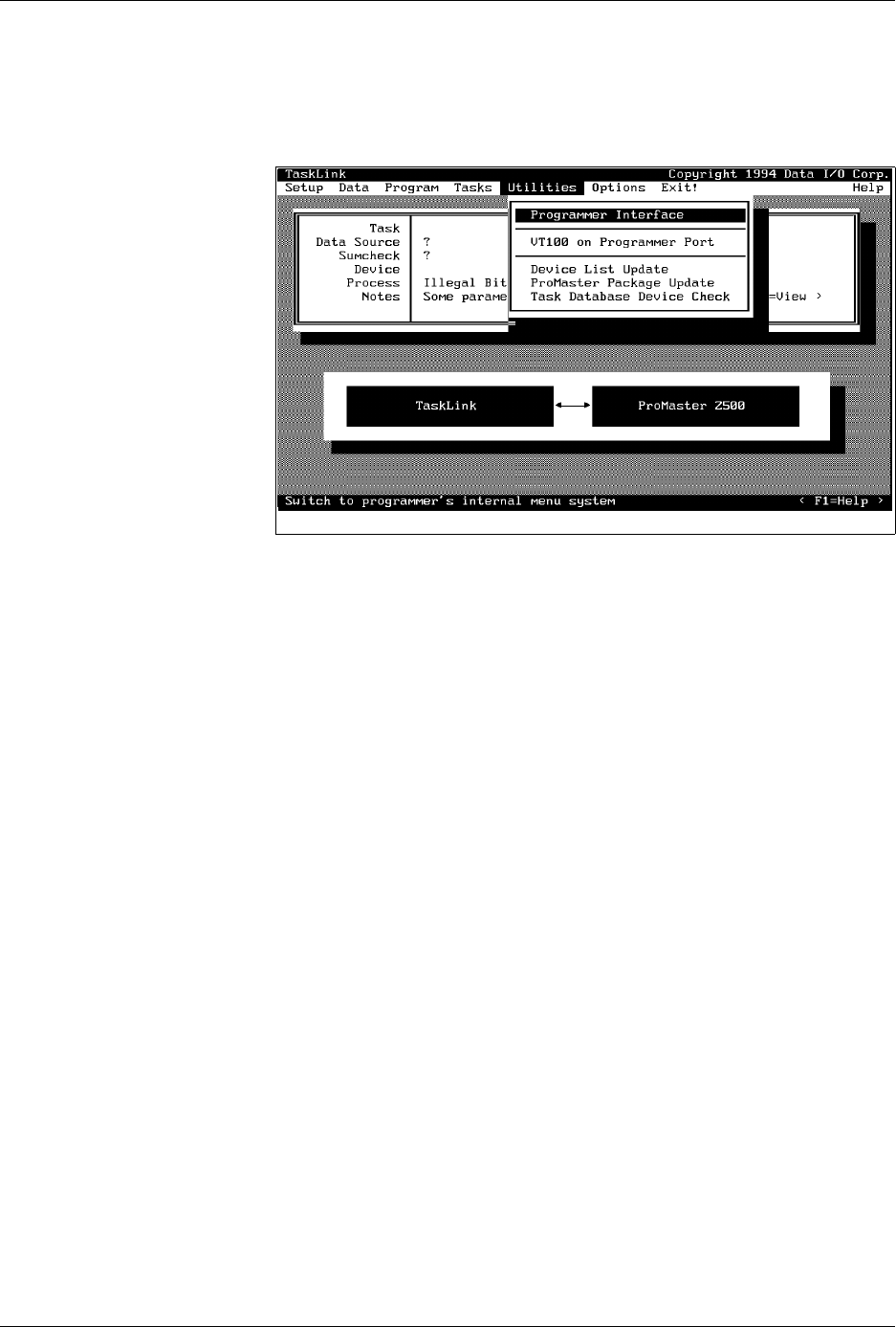
Programmer Interface
— When this command is selected, TaskLink
automatically displays a new set of menus so you can run diagnostic tests
on the programming electronics. Refer to Chapter 5 for more information
on running diagnostics on the programming electronics.
VT100 on Programmer Port
— Select this command when you update
the
Algorithm/System
disk(s). A description of this update procedure is
included with the
ProMaster 2500 User Notes
that are distributed
periodically.
Device List Update
and
Task Database Device Check
— After you
install the new Algorithm disk(s), follow the procedures to update the
device list and then to check the Task database before running your
existing Tasks or creating new ones. If you do not complete all the steps
in the update procedure, TaskLink may occasionally report error
messages indicating that the device in your Task could not be found.
ProMaster Package Update
—You will be notified in the
ProMaster 2500
User Notes
when support for new package types have been added, and
the Notes will instruct you to install new firmware EPROM(S) in the 2500.
TaskLink will need to be updated with the new package type(s) so it can
display them as options in the ProMaster 2500 dialog box. Select this
option to have TaskLink upload the new package information.
Figure 3-17
Utilities Pull-down Menu