2500_Users_Manual.pdf - 第282页
Repair and Repl acement Procedures 7-38 ProMa ster 25 00 U ser Ma nual When you have determined that the block needs to be replaced, follow the steps listed below. Th is procedure describes how to com pletely disassemble…

Repair and Replacement Procedures
ProMaster 2500 User Manual 7-37
10. Test the module by running a device-related operation using the
module.
Replacing the
Programming Block
on a PLCC Module
After a period of time, the protective coating on the programming block
(see Figure 7-28) may wear to the point that you begin to see a higher
number of device-related errors. If you have a second module of the same
pin count, you can confirm that wear is the source of these problems by
programming the same type of device on the second module and
comparing the yields.
CAUTION: To avoid possible damage to the system components, this
procedure should be performed only by a qualified service
technician.
Repair and Replacement Procedures
7-38 ProMaster 2500 User Manual
When you have determined that the block needs to be replaced, follow
the steps listed below. This procedure describes how to completely
disassemble the programming module so you can replace the top of the
programming block (see Figure 7-28).
You need the following items to complete this procedure:
• 1/16-inch hex driver
• 0.050-inch hex driver
• New programming block (top)
CAUTION: Remove all the configuration blocks from the module board
before you replace the programming block. The pins of a
contact set might hook on a block and bend or damage the
contacts.
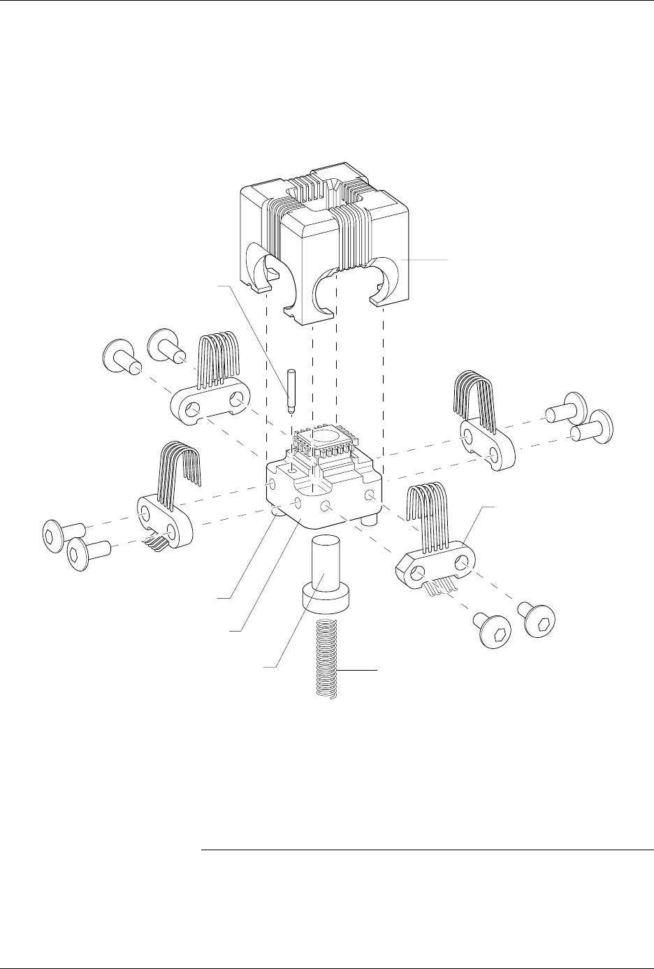
Figure 7-28
PLCC Programming Module (Exploded View)
PROGRAMMING BLOCK (Top)
1667-1
DEVICE EJECTOR PIN
PROGRAMMING BLOCK (Base)
BLOCK ALIGNMENT PIN (1 of 2)
CONTACT SET
(1 of 4)
GOLD PIN
DEVICE EJECTOR SPRING

Repair and Replacement Procedures
ProMaster 2500 User Manual 7-39
1. Remove the configuration blocks from all four sides (see Figure 7-22).
2. Turn the board upside-down and use the 0.050-inch hex driver to
remove the two screws holding the programming block to the
printed circuit board. Be careful not to strip the screws.
3. Hold the module in the upside-down position and gently pull the
board from the programming block assembly (see Figure 7-23).
4. Turn the block right-side up. The device ejector pin and ejector spring
are loose and will drop out into your hand (see Figure 7-24). Set these
aside; they will be reinstalled later.
5. Use a 1/16-inch hex driver to remove the two screws holding the
contact set in place.
6. Gently pivot the base of the contact set out from the programming
block and lift the set straight up.
7. Remove the other three contact sets.
8. Lift the top of the programming block off the base.
Note: The small gold pin in the base (see Figure 7-28) is not held in place. Be
careful not to lose it while the top is off the base.
9. Install the new top on the base. Make certain that the gold pin is
installed. You can insert the pin with either end pointing up.
10. Install one of the contact sets on the programming block.
Tilt the contact set slightly (see Figure 7-25) and gently insert the tips
into the receiving holes in the programming block. Make certain that
all the contact leads have correctly inserted into the holes before you
swing the set’s base into position against the block. Failure to have all
the tips seated correctly in their receiving holes could result in
damage to the contacts.
When the contact set is in position, insert and tighten the two hex
screws that hold it in place.
11. Install the three remaining contact sets.
12. Turn the assembled programming block upside-down and insert the
device ejector pin and spring into the programming block.
CAUTION: Remove all the configuration blocks from the module board
before you replace the programming block. The pins of a
contact set might hook on a block and bend or damage the
contacts.
13. Using the block alignment pins as guides, carefully slide the board
and block together.
14. Insert the two hex screws that hold the block to the board.
15. Insert the configuration blocks for the next device to be programmed.
Refer page 4-7 for more information on configuring the module.
16. Check the operation of the programming module using a device type
that gives you high yields.