2500_Users_Manual.pdf - 第95页
Task s and Ki ts 3-20 ProMa ster 25 00 U ser Ma nual Logging P rogrammi ng Statis tics Use the Session Data Logging... feature to a utomatically record sta tistics for each Task run in a file with a file_name. log extens…
Tasks and Kits
ProMaster 2500 User Manual 3-19
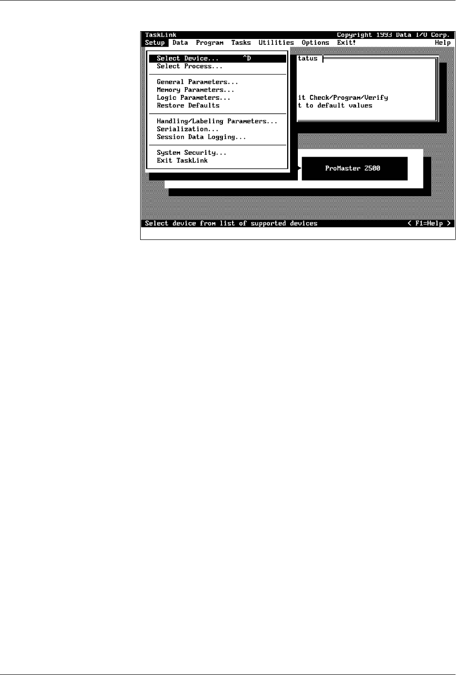
Figure 3-12
Commands Available under Setup

Tasks and Kits
3-20 ProMaster 2500 User Manual
Logging Programming
Statistics
Use the
Session Data Logging...
feature to automatically record statistics
for each Task run in a file with a
file_name.log
extension. From the
TaskLink main screen, press
Alt
and
S
to select the
Setup
pull-down
menu. Highlight
Session Data Logging...
and press
↵
. Figure 3-13 shows
the relationship between the Task Statistics screen (that appears by
default at the end of each Task) and the Session data logging file.
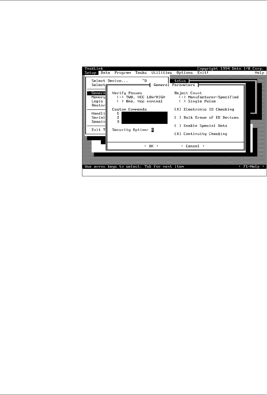
General Parameters
Most Tasks are run using the default values defined in this box. The
parameters that might be changed for operation with the 2500 are
described below. Other parameters displayed are intended to be used
with other products supported by TaskLink. Information on these
commands is available by pressing
F1
to invoke TaskLink’s online Help.
Only the commands used with the 2500 are described below.
Verify Passes
—Device manufacturers specify the high and low V
CC
voltage at which their devices will operate and output accurate data. The
2500 defaults to
two verify passes.
The device’s V
CC
pin is set to the
specification’s high V
CC
and the 2500 verifies that all bits in the device
compare with the RAM data. If this test passes, the 2500 sets V
CC
to the
low value and verifies each fuse in the device a second time. Selecting
One
directs the 2500 to test the device once using the nominal V
CC
level (+5V).
Custom Commands
— This is an optional CRC command field to control
the programming electronics with some special command that is not
supported by TaskLink. Refer to the Programming Electronics Computer
Figure 3-13
Log File Format Compared to Task
Statistics Screen
-
07-02-1993 17:12
?
LOGIC TASK
16v8.jed
0000B45C
LATTICE 16V8/A/BPLCC
CONT/IBC/PROG/TEST
73,0,1,1,0,0,0,0,0,0,0,0,1,1,0
?,?
Record Separator
Date & Time
Optional Session I.D. Name
Task Name
Data Source (Filename)
Programming Data Sumcheck
Device Type
Selected Process
Programming Results
First & Last Serial Numbers
filename.log
1959-1
(Insert Task Statistics Screen
and add leader line)
Tasks and Kits
ProMaster 2500 User Manual 3-21
Remote Control commands in Appendix E.
For example, you might use these commands if you want to program a
device but disable the verify option. The Edit Task dialog box does not
allow you to select this combination. From that box, Verify is
automatically enabled when Program is selected. Use the
023]
command
to disable the verify operation.
Security Option
— Some devices have a security fuse that, when
programmed, prevents any programming equipment from reading its
data. Set this value to 3 to program the security fuse in most PLD devices.
The main array of device fuses are verified before the security fuse is
programmed. If the main array fuses pass, the security fuse is
programmed and the 2500 will no longer be able to read the original
sumcheck from the device. The only way to confirm correct data in a
device after its security fuse has been programmed is to run structured test
vectors.
Enable Special Data
— Used by some devices to enable special options
they offer. The option depends on the device being programmed. For
example, some microcontroller devices have extra security fuses that can
be enabled only when this parameter is set. Refer to the 2500 Device List
footnotes to see if any special options are available for the device in your
Task.
Continuity Checking
— This option allows you to enable or disable
continuity checking on some devices. Under most circumstances you
would not disable this check as it provides important information about
how the device is seated in the programming module. If the test is
disabled and a device is not making good contact in the programming
module, the device will fail with either a programming or verify error. For
some devices, the continuity test is an integral part of the programming
algorithm and cannot be disabled even when it is not selected on the
screen. Continuity checking is enabled when TaskLink is shipped.
Figure 3-14
General Parameters Dialog Box