2500_Users_Manual.pdf - 第272页
Repair and Repl acement Procedures 7-28 ProMa ster 25 00 U ser Ma nual 24. Place the baffle plate back o n the beam and then reinstall al l of the screws in the order sho wn in Figure 7-1 8. 25. Carefully re-assemble all…
Repair and Replacement Procedures
ProMaster 2500 User Manual 7-27
10. Use a 6/64-inch hex wrench to remove the two screws that hold the
air cylinder pin in place.
11. Hold the beam in place while you use a 3/32-inch hex wrench to
gently push the air cylinder pin through the beam.
12. Gently lift the beam up and away from the beam shafts.
13. Remove the two 1/16-inch set screws in the beam motor drive pulley.
14. Disconnect the beam motor cable.
15. Remove the single 3/32-inch hex mounting screw in the beam head
pulley.
16. Pull up the beam head pulley and remove the beam rotation belt.
17. Remove the motor drive pulley.
18. Use a 1/16-inch hex wrench to remove the four motor mounting
screws, then remove the beam head rotation motor.
19. Use a 3/32-inch hex wrench to remove the two air quick connects
(insert the hex wrench into the quick connect openings).
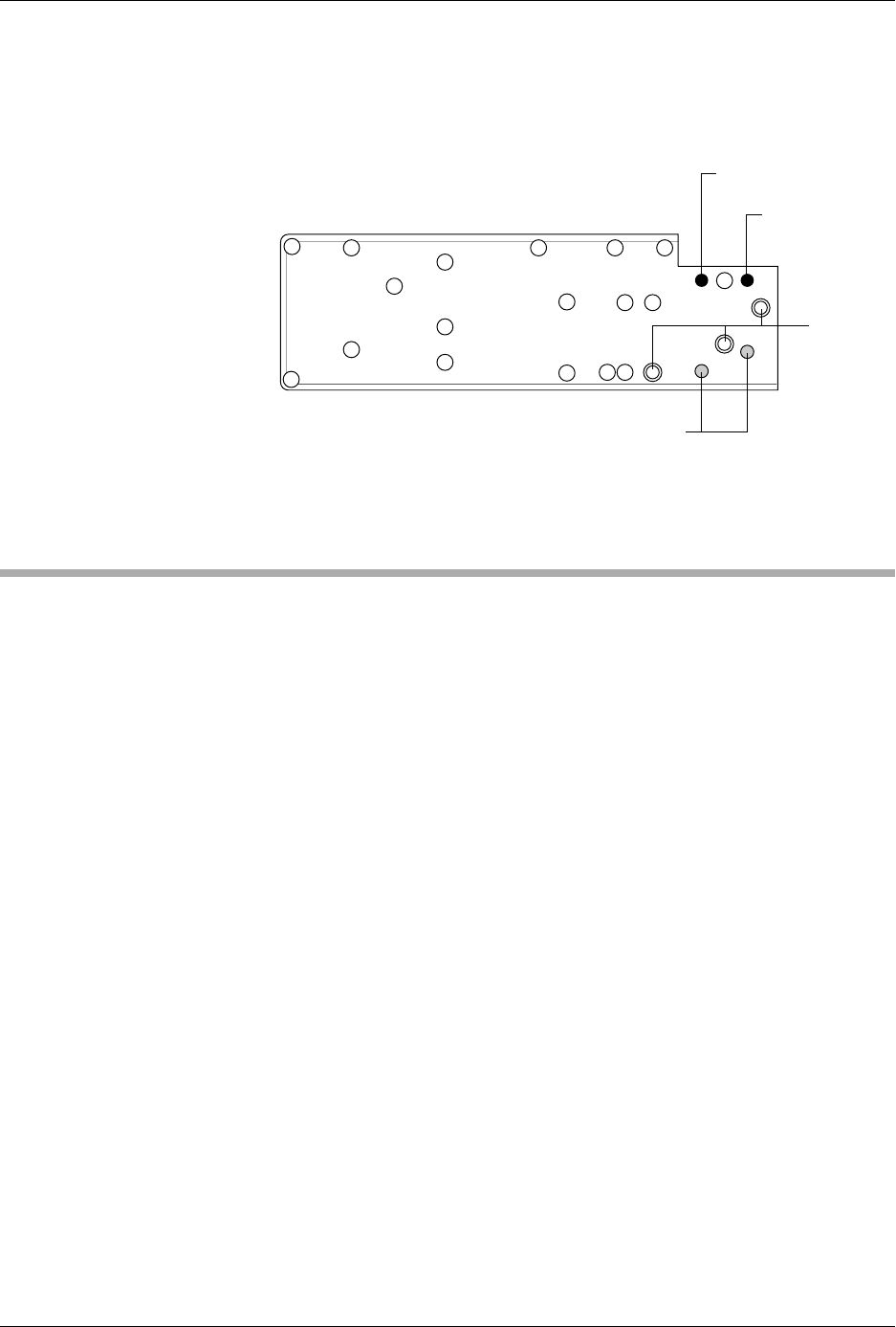
20. Use a 3/32-inch hex wrench to remove 20 screws in the baffle plate.
21. Use a 1/4-inch hex wrench to remove the three remaining pan head
screws in the baffle plate.
22. Peel off the old air channel gasket.
23. Place the new air channel gasket onto the baffle plate.
Note: Make sure the air channel gasket does not block any air and vacuum holes.
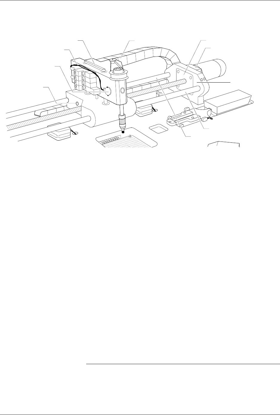
Figure 7-17
Beam Cable and Switch Locations
2287-1
VACUUM SENSOR CABLE
CABLE HARNESS GUIDE
BEAM TRAVERSE
MOUNTING BLOCK
RIGHT END PLATE
LIMIT BAR
BEARING COVER PLATE
REAR CARRIAGE SHAFT
FRONT COVER SHAFT
VACUUM SENSOR
SWITCH
AIR CYLINDER
PIN SCREW
(1 on each side)
Repair and Replacement Procedures
7-28 ProMaster 2500 User Manual
24. Place the baffle plate back on the beam and then reinstall all of the
screws in the order shown in Figure 7-18.
25. Carefully re-assemble all of the disconnected cables and components.
Disk Drive Replacement
This procedure describes the steps required to remove and replace the
disk drive.
Replacing the Disk
Drive
If the disk drive fails, follow the steps below to replace it.
1. Turn off the 2500 and remove the power cord.
2. Disconnect the disk drive power cable.
3. Disconnect the disk drive ribbon cable.
4. Use a 3/32-inch hex wrench to remove the two screws from under
the disk drive mounting plate. Remove the disk drive.
5. Use a 3/32-inch hex wrench to attach the new disk drive to the disk
drive mounting plate and reconnect the power and ribbon cables.
Figure 7-18
Baffle Plate Reinstallation
LO QUICK
CONNECT
(Gray)
HI QUICK
CONNECT (Black)
E CHAIN SCREWS
2338-1
1/4"
SCREWS
1
11
15 5 8 13
19
21
17
1274
6910
16
3
2
14
18
20
22
23

Repair and Replacement Procedures
ProMaster 2500 User Manual 7-29
Keyboard/Display Assembly Replacement
This procedure describes the steps required to remove and replace the
keyboard/display assembly.
Replacing the
Keyboard/Display
Assembly
If the keyboard/display assembly fails, follow the steps below to replace
it.
1. Turn off the 2500 and remove the power cord.
2. Use the flat edge of a flat-head screwdriver (or a table knife) to pry up
the bottom left and top sides of the keyboard/display assembly,
which is affixed with two-sided tape.
CAUTION: Do not pry up the right side of the display.
3. Pull the keyboard/display assembly away from the 2500.
Note: The keyboard/display assembly is held in place with double-sided tape.
4. Remove the two cables that connect the keyboard/display assembly
to the controller board.
5. Apply double-sided tape to the underside of the new keyboard/
display assembly.
6. Connect the two controller board cables to the new keyboard/display
assembly.
7. Press the new keyboard/display assembly into place.
Programming Module Components Replacement
These procedures describe the steps required to replace failed
components on programming modules.
Replacing Contacts
on a DIP Module
Use the following procedure to replace the contact sets on a
programming module. Replace both sides at the same time.
1. Mark the module on the end next to the narrower end of the circuit
board. You must reinstall the module on the board in the correct
orientation. It is possible to reinstall the module backwards on the
board.
2. Remove the four hex screws from the underside of the programming
module board and remove the printed circuit board (see Figure 7-19).