2500_Users_Manual.pdf - 第126页
Operation 4-12 ProMa ster 25 00 U ser Ma nual Installing a Programming Module Install the n ew programmin g module with th e silk-screened X4 to the right (toward the input track). Guide pins on the 2500 will not allow y…

Operation
ProMaster 2500 User Manual 4-11
Table 4-1
ProMaster Programming Module Configuration Chart
Programming
Module Type Pin Count
Connector X1 Connector X2 Connector X3 Connector X4
PLCC-20-1 20 Open Open Open Open
PLCC-20-2 20 Open 20A Open 20A
PLCC-28-1 28 Open Open Open Open
PLCC-28-2 28 Open 28A Open 28A
PLCC-28-3 28 Open 28B Open 28A
PLCC-28-4 28 28A Open 28A Open
PLCC-28-5 28 28C 28D 28E 28B
PLCC-32-1 32 Open Open Open Open
PLCC-32-2 32 Open 32A Open 32A
PLCC-44-1 44 Open Open Open Open
PLCC-44-2 44 Open 44A Open 44A
PLCC-44-3 44 44B 44C 44B 44A
PLCC-52-1 52 Open Open Open Open
PLCC-52-2 52 52A Open 52B Open
PLCC-68-1 68 Open Open Open Open
PLCC-68-2 68 68A 68A 68A 68A
PLCC-68-3 68 68C 68B 68C 68B
PLCC-68-4 68 68D 68D 68D 68D
PLCC-84-1 84 Open Open Open Open
PLCC-84-2 84 84B 84C 84B 84A
Operation
4-12 ProMaster 2500 User Manual
Installing a
Programming
Module
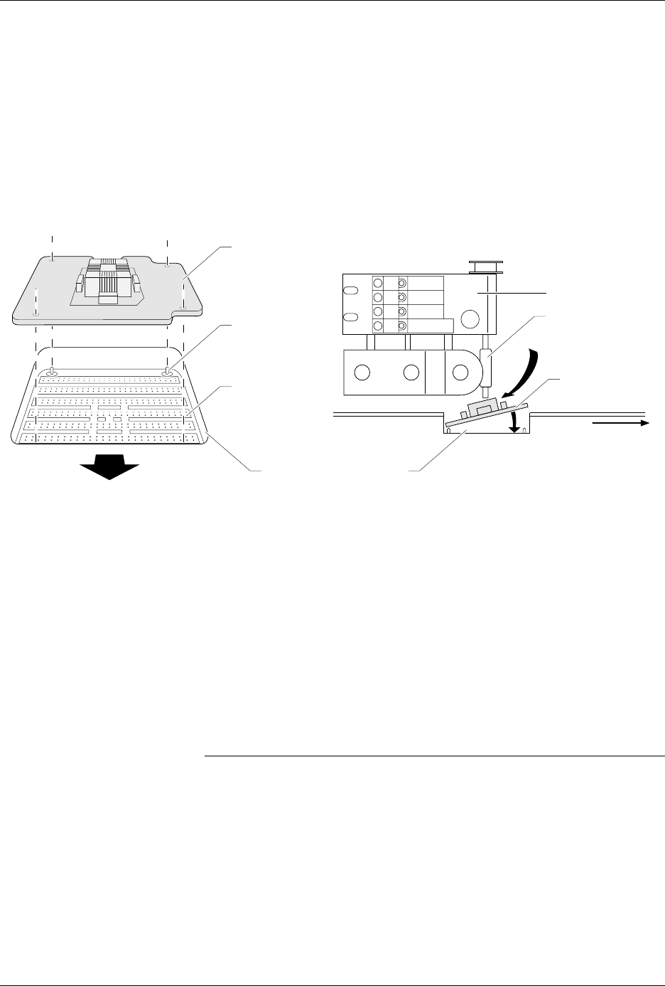
Install the new programming module with the silk-screened
X4
to the
right (toward the input track). Guide pins on the 2500 will not allow you
to install the module backwards. If the beam is centered over the
programming station, insert the module at an angle into position as
shown in Figure 4-8.
The 2500 automatically completes the installation of the module on the
programming pin interface (SPA pins) when you start the Task. System
software controls the release of the module between Tasks and when the
operator requests it by pressing
STOP
(on the 2500’s keyboard) twice.
Pressing
START
closes the clamps on the module again.
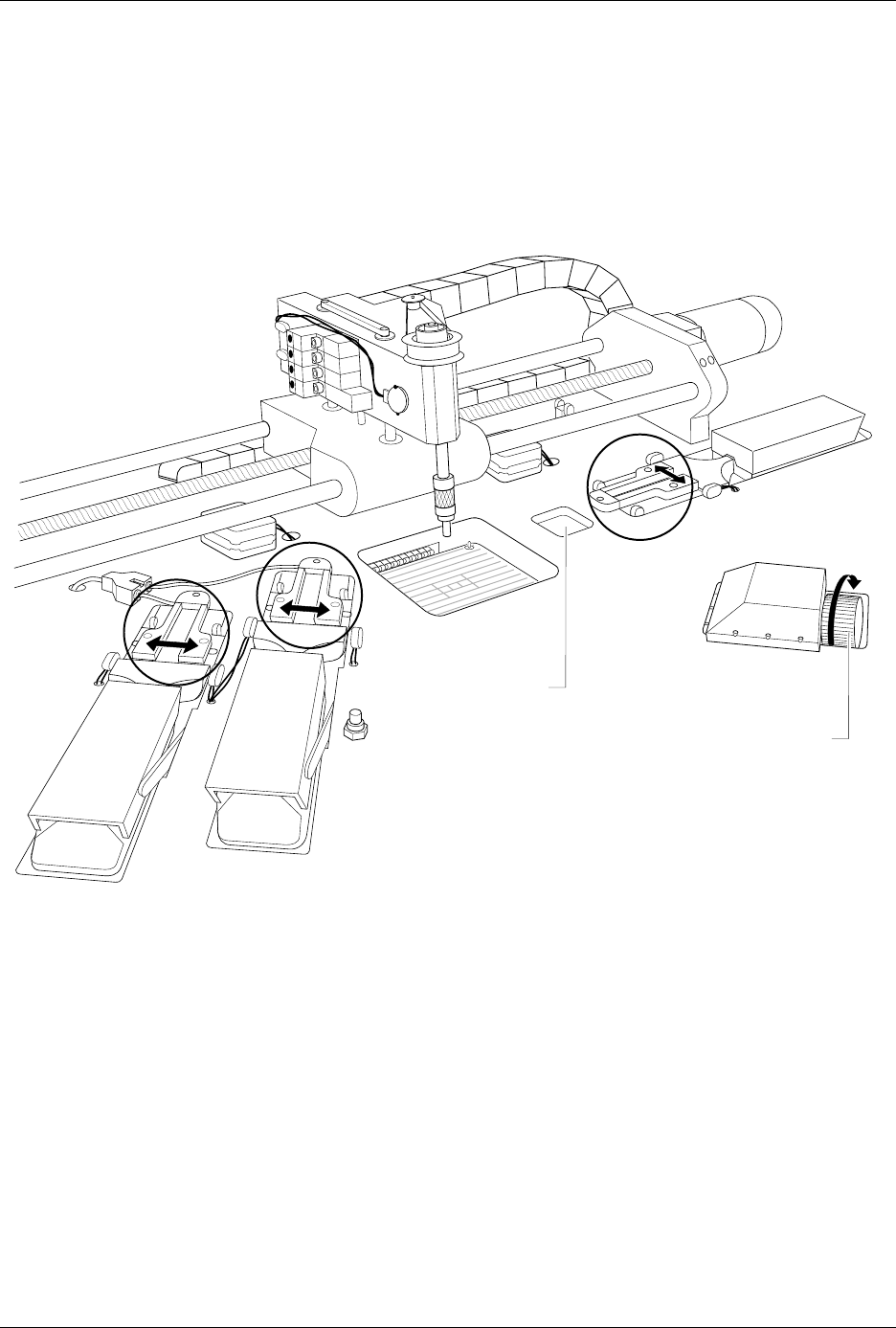
Adjusting the Track
Width
Whenever a new Task requires that you change device package type, you
must adjust the track width for the new device. All three track sections
are adjusted by turning the track width adjustment knob (see Figure 4-9).
To adjust the track width, perform the following procedure.
CAUTION: Be sure to adjust the track width according to the following
procedure. Closing the track on a device while it is in the
track may compress the leads and damage the device.
Figure 4-8
Installing a Programming Module
1767-1
FRONT OF 2500
SPA PINS
PROGRAMMING
MODULE
PROGRAMMING STATION
X2
X4
3
X
ALIGNMENT
PIN (1 of 4)
VIEW FROM THE SIDE
FRONT
OF 2500
BEAM
CHUCK
PROGRAMMING
MODULE
Operation
ProMaster 2500 User Manual 4-13
1. Remove devices from all three track sections.
2. Turn the track width adjustment knob counterclockwise until the
track is at its narrowest setting. This step is important because it
prepares the three track sections to be adjusted together and
uniformly.
3. Begin opening (widening) the track.
4. Before the track opens as wide as the device you will be using, place
one of the devices (with its leads up) in the input track next to the
programming station’s stop guide. See Figure 4-10.
The device should be resting on the rear wall of the track (see Figure
4-10) and should block the optic.
Figure 4-9
Adjusting the Track Width — Turning the knob clockwise opens all three track sections together.
TRACK WIDTH
ADJUSTMENT KNOB
DEVICE INDENT
1856-2