2500_Users_Manual.pdf - 第32页
Introduc tion 1-10 3/97 ProMast er 25 00 Use r Man ual Beam — Wit h a chuck on the beam head , a pick-and-p lace method is used to gently transport devices. Informa tion in the Task instructs the beam to rotate the devic…
Introduction
ProMaster 2500 User Manual 3/97 1-9
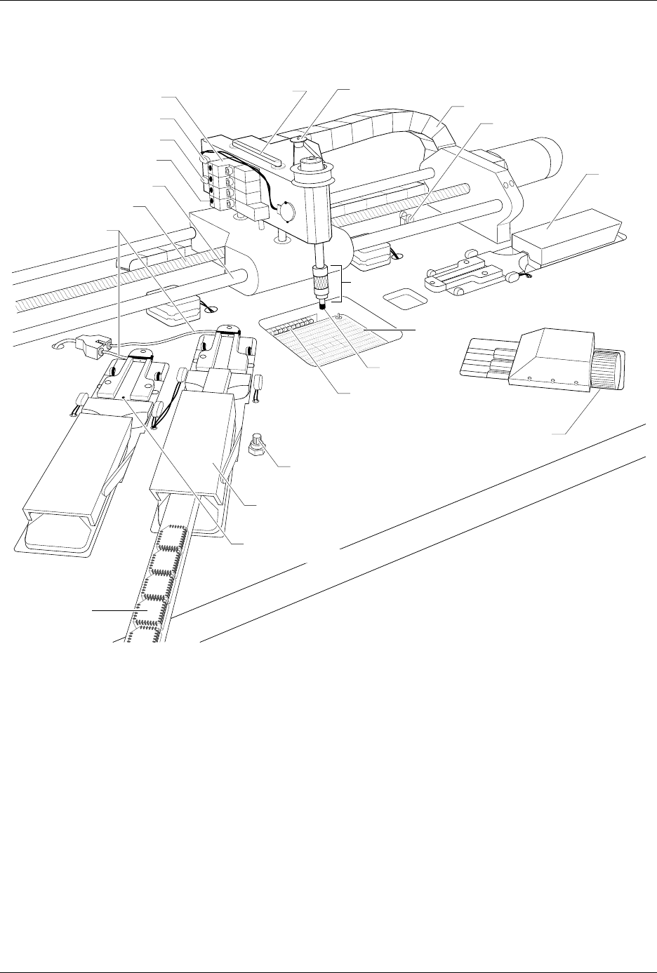
Figure 1-7
Beams and Programming Station Component Identification Drawing
BEAM HOME OPTIC
1766-1
BEAM ROTATE MOTOR
BEAM SOLENOID (1 of 4)
BEAM DOWN OPTIC
BEAM UP OPTIC
SOLENOID LED (1 of 4)
CHUCK
CABLE HARNESS GUIDE
INPUT
TUBE
HOLDER
TRACK WIDTH
ADJUSTMENT KNOB
MODULE CLAMP
(1 of 2)
TRACK AIR ADJUSTMENT KNOB
CHUCK TIP
SPA PINS
DEVICES IN
OUTPUT TUBE
TRACK HEIGHT
ADJUSTMENT SCREW
LIMIT BAR
LEAD SCREW
FRONT CARRIAGE SHAFT
TRACK AIR LINES
OUTPUT TUBE HOLDER 1

Introduction
1-10 3/97 ProMaster 2500 User Manual
Beam
—With a chuck on the beam head, a pick-and-place method is used
to gently transport devices. Information in the Task instructs the beam to
rotate the device so that programming and labeling are performed with
the correct device orientation. The beam’s position is automatically
calibrated each time the system is initialized.
Chuck
—Located on the end of the beam, the chuck achieves an air-tight
seal on the device so the beam’s vacuum can pick up and release devices
as they are processed.
Programming Station
—Opening in the main plate through which the
SPA pins can be seen. This is where the programming module is installed
and devices are programmed.
Programming Module
—Installed over the SPA pins of the 2500, serves
as the socket for the device during the programming operation. Devices
are inserted by the beam into a DIP, PLCC, or SOIC programming
module, where they are programmed or tested by the system.
Internal Features
The internal features include all the component parts located beneath the
main plate, in the 2500’s base. These include the system’s power supplies,
firmware and controller board, motors, programming electronics, and
other components.
WARNING:Raising the main plate with power on will expose you to
harmful, high voltage. Only trained service technicians
should perform the diagnostic tests that require lifting the
main plate while the power is on.
Introduction
ProMaster 2500 User Manual 3/97 1-11
Front Panel
The primary features of the 2500’s front panel are described below (see
Figure 1-8).
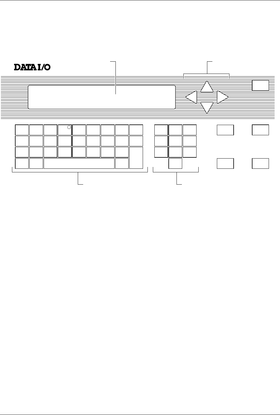
Control Keys START
—Pressing
START
indicates that you are ready to begin the
operation you have selected.
STOP
—Pressing
STOP
once suspends system operation so you can
make an adjustment. Refer to the STOP commands described in the
Appendix B. Pressing
STOP
twice releases the programming module
clamp.
RESET
—Pressing
RESET
while in local mode stops the operation being
performed and returns you to the Main Menu (except in the Diagnostics
EEPROM test when pressing
RESET
returns you to the Diagnostics
Menu). After you press
RESET
, all counters are reset, and the 2500 is
ready to begin another operation.
CAL
—Pressing
CAL
calibrates labels to determine their reference
position on the label liner. This reference point is required for correct
label printing and application to the device.
Figure 1-8
The ProMaster 2500 Front Panel
!
_
$
"
*
,
#
:
;
=
<
%
~
>
&
@
?
'
\
.
(
+
/
)
-
c
1765-1
SHIFT
A
J
S
B
K
T
DEL
C
L
U
D
M
V
E
N
W
SPACE
F
O
X
G
P
Y
H
Q
Z
LOWER
CASE
I
R
ENTER
1
4
7
2
5
8
0
3
6
9
STOP
START
ON
DISPLAY ARROW KEYS
KEYBOARD NUMERIC KEYS
RESET
CAL