2500_Users_Manual.pdf - 第254页
Repair and Repl acement Procedures 7-10 ProMa ster 25 00 U ser Ma nual 10. Remove the orbital ca m from the moto r shaft. Now you ar e ready to rem ove the i nput orbita l motor . 11. Unplug the Molex motor cable J-12. T…
Repair and Replacement Procedures
ProMaster 2500 User Manual 7-9
4. Remove the two 3/32-inch hex screws that hold the rear orbital
alignment block to the underside of the main plate. Slide the rear
orbital alignment block off the dowel pin, and let the block dangle
from the cables.
5. From above the main plate, remove the two 3/32-inch hex screws
that hold the front orbital alignment block to the main plate. Remove
the front orbital retaining block from the underside of the main plate.
6. Support the left side of the orbital assembly while you remove the
7/64-inch hex retaining screw (with the white plastic standoff) on the
right support brace.
7. Remove the 3/32-inch hex screw that holds the grounding strap to
the right support brace.
8. Carefully slide the left side of the input orbital assembly off the
orbital cam spindle. Be careful that the white bushing between these
two is not lost or damaged.
9. When the assembly is off the spindle, slide it to the left until it is free
from the right support brace. Let it dangle from the cables.
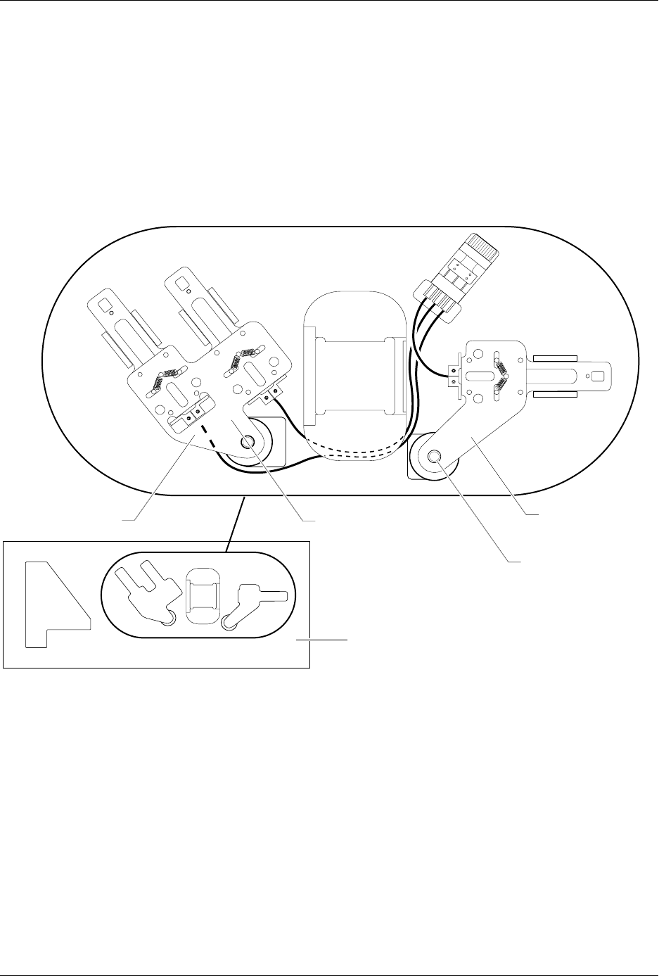
Figure 7-8
Input and Output Orbital Assemblies
2307-1
INPUT ORBITAL
ASSEMBLY
OUTPUT ORBITAL
ASSEMBLY
MAIN PLATE (Underside)
CAM SPINDLE
CAM SPINDLE
Repair and Replacement Procedures
7-10 ProMaster 2500 User Manual
10. Remove the orbital cam from the motor shaft. Now you are ready to
remove the input orbital motor.
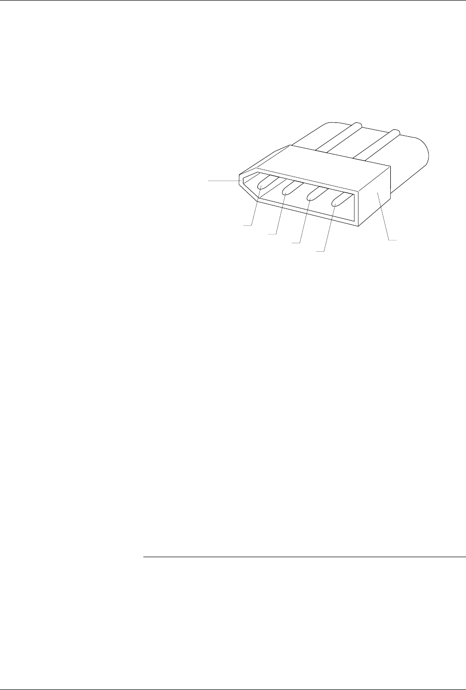
11. Unplug the Molex motor cable J-12. The end of this connector is
located under the main plate and will not fit through the main plate
hole. Remove the four pins in the connector to free the cable. Note the
wire colors and positions in the connector (see Figure 7-9).
12. Use a Molex pin extractor tool to remove the four pins from the white
plastic connector.
13. After removing the four pins, pull the cable through the main plate.
14. From below the main plate, remove the four 1/16-inch hex screws
that hold the input orbital motor to the main plate.
15. Lower the main plate and remove the input orbital motor.
16. Place the new input orbital motor in position on the main plate. Make
sure the power cable is oriented to the right side of the new input
orbital motor.
17. Guide the motor cable through the hole in the main plate.
18. Insert the four motor wires into the white plastic Molex connector. Be
sure to insert the wires in the same order (and orientation) as shown
in Figure 7-9.
19. The input orbital motor shaft has one flat side. Turn the shaft until the
flat edge faces the front of the 2500.
20. The orbital cam has a small hole on its outer edge. Position the cam
on the motor shaft so this small hole is positioned on the right side
(input side) of the shaft.
CAUTION: As you reinstall the input orbital assembly, make sure the
white bushing that fits over the spindle stays in position.
21. Reinstall the input orbital assembly (in reverse order from the
procedure in steps 6-9 above).
22. Reinstall the front and rear orbital alignment blocks.
Figure 7-9
Note the Wire Colors and Positions
2286-1
GREEN
POINT
BLACK
BLUE
RED
FLAT END
Repair and Replacement Procedures
ProMaster 2500 User Manual 7-11
23. Rotate the orbital cam to make sure it spins freely and does not rub
against the underside of the main plate. If you feel or hear the cam
rubbing against something, grasp the outer edge of the cam and
gently pull it approximately 3/32 of an inch away from the underside
of the main plate and recheck it again.
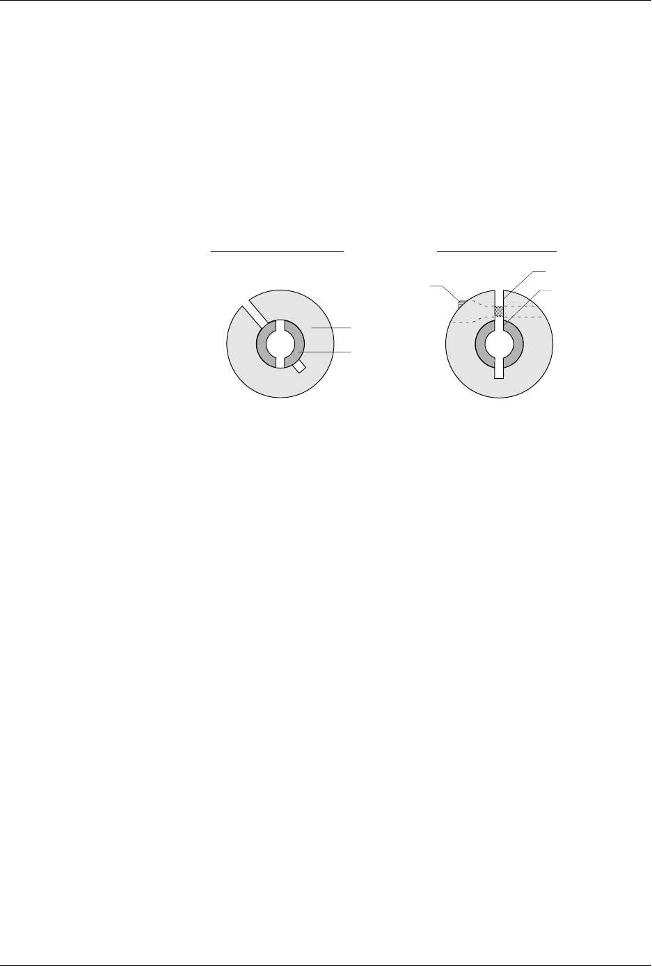
24. Install the collar over the cam spindle. The slit in the collar must be
aligned with the slit in the spindle (see Figure 7-10).
25. Turn the orbital cam one final time to check for smooth rotation with
no rubbing.
Replacing the
Output Orbital
Motor
Follow the steps below to access and replace the output orbital motor.
1. Turn off the 2500 and remove the power cord.
2. Remove the PE assembly, as described on page 7-3.
3. Locate the round output orbital motor collar. Loosen the 7/64-inch
hex screw and remove the motor collar.
4. Disconnect the Molex motor cable J-13. The end of this connector is
located under the main plate and will not fit through the main plate
hole. You must remove the four pins in the connector to free the
cable. Note the wire colors and the wire positions in the connector
(see Figure 7-9).
5. Use a Molex pin extractor tool to remove the four pins from the white
plastic connector.
6. After you've removed the four pins, pull the cable through to the top
of the main plate.
7. Remove the 3/32-inch hex screw that holds the grounding strap to
the left support brace.
8. Remove the two 3/32-inch hex screws that hold the optic block to the
underside of the main plate. Slide the optic block off the dowel pin.
9. From above the main plate, remove the two 3/32-inch hex screws
holding the right orbital alignment block to the main plate. Slide the
block out and set it aside.
Figure 7-10
Align the Slit in the Collar with
the Slit in the Spindle
2297-1
INCORRECT ALIGNMENT CORRECT ALIGNMENT
SLIT IN COLLAR
SLIT IN SPINDLE
HEX SCREW
COLLAR
SPINDLE