2500_Users_Manual.pdf - 第194页
Preven tive Maint enance 5-40 ProMa ster 25 00 U ser Ma nual The solenoids perf orm the follow ing operat ions (con firm that LEDs on the solenoids turn on for the duration of each test) : • Blower — Turns on low air pre…
Preventive Maintenance
ProMaster 2500 User Manual 5-39
To see the LEDs on this board (located in the 2500’s base), loosen the two
corner screws that hold the main plate in position on the base and raise
the main plate. Figure 5-19 shows the location of the board. An LED on
that board illuminates when the solenoid control circuitry is sending a
signal to activate the solenoid.
If the LED on the solenoid is not on during the test, make sure that the
logic drive circuit associated with that solenoid is operating correctly.
Refer to the table below to determine the LED associated with each test. If
the LED is on during the test, you can be fairly certain that the solenoid
driver is getting the proper logic signal.
Refer to the table below to select and enter the test number for each
solenoid you wish to evaluate. Press
ENTER
. Then press
START
to begin
the test.
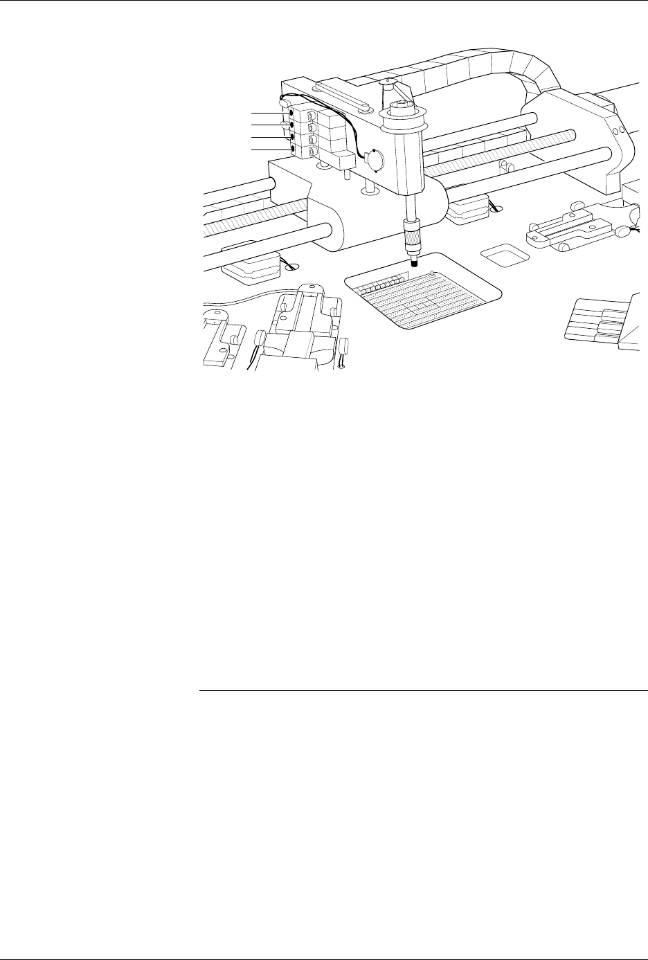
Figure 5-16
Solenoids on the Beam
(test numbers shown)
Position/Function
Solenoid
Test No.
Board
LED No.
Underside of Main Plate, left side of PE
Blower (output track air)
Cutoff (low air pressure to beam)
2
3
S2
S3
Left side of Beam Head
Beam Up/Down
Blow Off (device release)
High pressure (to lower beam)
Vacuum
4
5
6
7
S4
S5
S6
S7
Underside of Main Plate, right side of PE
Clamp (programming module) 8 S8
Unused
N/A 1 S1
1940-1
7
6
5
4

Preventive Maintenance
5-40 ProMaster 2500 User Manual
The solenoids perform the following operations (confirm that LEDs on
the solenoids turn on for the duration of each test):
•
Blower
— Turns on low air pressure to the output tracks. There is no
air on the input track.
•
Cutoff
— Turns low air pressure to the beam on and off. If you are
running all tests, perform the cutoff test first when you enter the
diagnostic tests. At the start of the diagnostic tests, the beam should
be up. Pressing
3
directs air to the beam, allowing it to rise.
Note: After you run this test you must press
RESET
to exit the solenoid tests
and then reselect the solenoid tests. If you do not press
RESET
, the Beam
Up/Down and the High Pressure tests will not operate correctly.
•
Beam Up/Down
—Directs low air pressure to raise the beam.
Pressing the
4
key allows the beam to lower.
•
Blow Off
—Turns on low air pressure to the chuck tip to assist in
releasing a device. Feel for air blowing out of the chuck tip.
•
High Pressure
—Turns on high pressure. The beam will lower
quicker than the Beam Up/Down test, which uses low air pressure.
•
Vacuum
—Turns on the vacuum generator. Place your finger over
the end of the chuck and feel the vacuum.
•
Clamp
—Activates the programming module holding clamps. They
should both advance and clamp the module.
To exit the solenoid test and return to the Diagnostic menu, press
E
and
then
ENTER
. To exit the solenoid test and return to the 2500’s main
menu, press
RESET
.
Motor Test
To select Motor Test from the Diagnostics menu, press
3
. The 2500
displays:
WARNING:To perform the motor tests, the hood has to be raised for
better visibility. To avoid electrical shock or mechanical
injury, these tests should be performed only by a service
technician trained on electromechanical equipment.
The beam moves quickly. To avoid injury, keep your
hands, hair, and loose clothing away from the path of the
beam while running these tests.
Refer to the motor test table and Figure 5-17. Press the number for the
motor you wish to test, and then press
START
to activate the motor.
Press
CAL
to reverse the rotation direction.
PRESS NUMBER TO TEST MOTOR, E TO EXIT
1 - BEAM FORWARD 4 - TUBE INPUT
2 - BEAM REVERSE 5 - TUBE OUTPUT
3 - BEAM ROTATION 6 - LABELER
Preventive Maintenance
ProMaster 2500 User Manual 5-41
Note: The beam traverse motor (tests 1 and 2) may appear to stall or fail. This
could be caused by a dirty or dry lead screw. Refer to page 5-63 for the lead
screw cleaning and lubricating procedure. If this does not resolve the
problem, adjust the motor speed by entering the STOP command
LOWER CASE
+
M
, described in Appendix B.
CAUTION: Be sure to open the hood during traverse motor test 1 to
prevent the beam from hitting the hood shock mount.
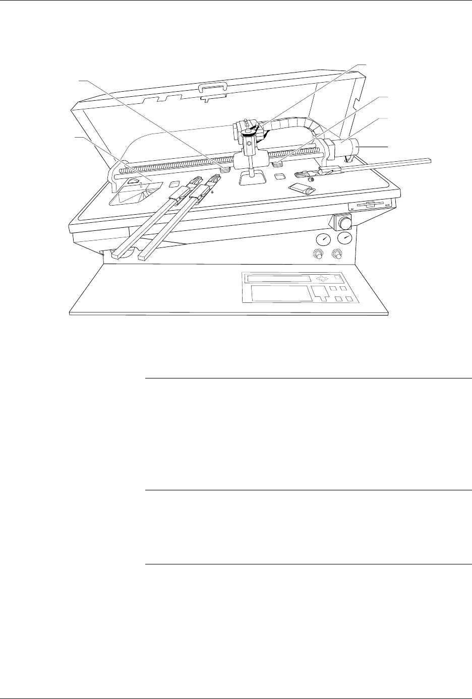
Figure 5-17
Location of the Motors
Test No. Motor Description
1Beam Forward
2Beam Reverse
3 Beam (Head) Rotate
4Tube Input (Orbital)
5Tube Output (Orbital)
6Label Drive
1942-2
(5) TUBE OUTPUT
(1 + 2) BEAM
TRAVERSE
(6) LABELER
(Hidden)
(4) TUBE INPUT
(3) BEAM ROTATE
MOTOR ENCODER