2500_Users_Manual.pdf - 第52页
Insta llation a nd Se tup ProM aster 25 00 User Manua l 2-9 Setting Up the Dot Matrix Printer The following sections describe the setup procedures that need to be checked and performed on the do t matrix printer before l…
Installation and Setup
2-8 ProMaster 2500 User Manual
Installing and
Removing Chucks
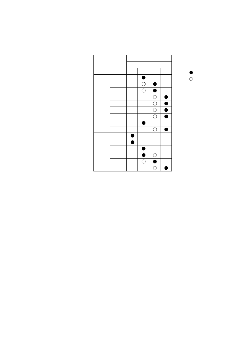
Three chucks are provided with the system. Each chuck has a different
tip diameter that corresponds to the size and dimensions of different
devices. Figure 2-7 shows the appropriate chuck for each supported
package type.
CAUTION: Chucks are released from the beam suddenly. When changing
a chuck, do not position the beam over the label application
area, the SPA pins, or programming module. The sudden
release of the chuck from the beam may damage those
components. Usecaretopositionthebeamonlyinthe area
described below before attempting to remove chucks.
Change the chuck with the beam directly over one of the two main plate
device recesses. Keep the beam raised by holding it up with two fingers
while you use a downward pulling/twisting motion to remove the
chuck. With one hand on the beam for support, insert the new chuck by
lifting it straight up until it snaps into position.
Figure 2-7
Chuck Selection Chart
DEVICE
TYPE
PLCC
DIP
LMN
20-PIN
28-PIN
32-PIN
44-PIN
52-PIN
68-PIN
84-PIN
300 mil
600 mil
1850-3
Recommended
Alternate
SOIC 150 mil
220 mil
300 mil
330 mil
420 mil
500 mil
K
CHUCK
ProMaster 2500
Installation and Setup
ProMaster 2500 User Manual 2-9
Setting Up the Dot
Matrix Printer
The following sections describe the setup procedures that need to be
checked and performed on the dot matrix printer before labels can be
printed properly.
Checking the Application
Plate Height
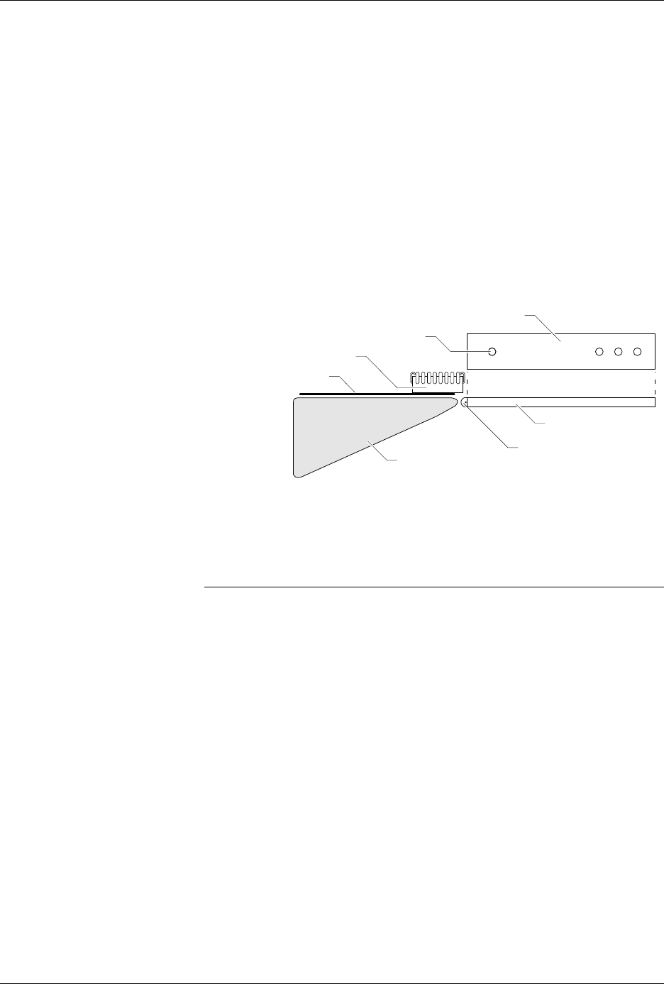
Make sure the dot matrix printer’s application plate is aligned correctly
by holding a device in your fingers in the “dead bug” position, with the
leads pointing up, and sliding it across the application plate, over the
press bearings, and onto the bearing plate (see Figure 2-8). The device
should move smoothly across the press bearings.
If device travel is not smooth, use a 7/64-inch hex wrench to loosen
(raise) or tighten (lower) the screw on the left side of the plate (near the
bearings) until a smooth transition is achieved (see Figure 2-8).
Loading Labels
Labels are positioned on a non-adhesive liner material so they will peel
easily as they advance around the label platen’s point. The label part
number is written on a label attached to the inside of the label roll.
Note: The label part number is marked on the inner cardboard reel. You can
identify a roll of ProMaster 2500 labels by the “QF” prefix in the part
number. Labels for other Data I/O products will look the same but cannot
be used on the 2500.
Figure 2-8
Adjusting Plate Height
1853-1
PLATEN
APPLICATION PLATE
PRESS BEARINGS
BEARING PLATE
SCREW (1 of 4)
DEVICE
TOP VIEW OF BEARING PLATE
Installation and Setup
2-10 ProMaster 2500 User Manual
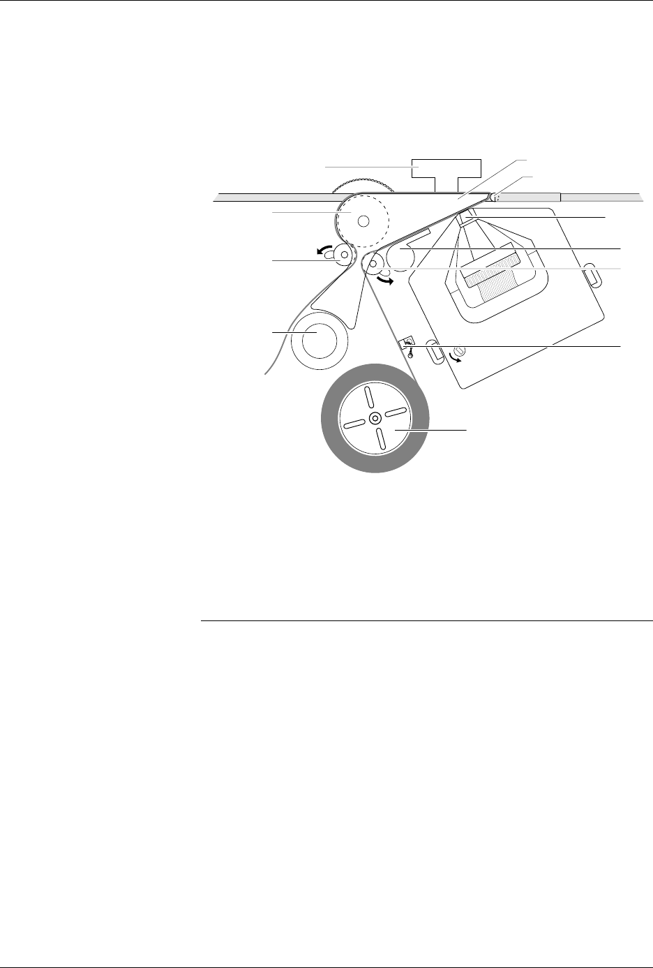
Refer to Figure 2-9 and follow these steps to install a roll of labels:
1. Raise the application plate, and release rollers
B
and
F
by sliding
them in the direction shown by the arrows in Figure 2-9. This
prepares the path of the labels to be threaded through the labeler.
2. Remove the label reel cover (see Figure 2-9).
3. If labels are already installed, unthread the liner, and remove the
label roll by putting your thumbs into the cut-outs in the supply reel
and rocking the roll back and forth as you pull it off.
4. Install the labels on the supply reel so that the label liner passes to the
left of optic
A
(see Figure 2-9).
Note: Do not tighten the label roll on its core. The roll is intentionally wrapped
loosely so that high temperature and humidity do not cause the labels to
peel incorrectly.
5. Replace the label reel cover over the label reel.
6. Unroll approximately two feet of liner, and thread it around the left
of roller
B
, between
C
and
D
, and then between the platen and press
bearings.
7. Move roller
B
to the left so it pinches the label liner and holds it in
position. Ensure that the labels are fully aligned between the
underside of the platen and above
C
and
D
.
Figure 2-9
Loading Labels in the Dot Matrix
Printer
1851-2
D
PRESS BEARINGS
PLATEN
APPLICATION PLATE
E
LABEL REEL COVER
F
B
C
A
G