2500_Users_Manual.pdf - 第85页
Task s and Ki ts 3-10 ProMa ster 25 00 U ser Ma nual Note: Your company should establish a standard orientation for each device package typ e (DIP, sq uare PLCC, 32 -pin PLCC, S OIC) so that all operat ors inse rt de vic…
Tasks and Kits
ProMaster 2500 User Manual 3-9
•
Label
—Select this parameter to label the devices. Devices do not
have to be programmed (or verified) and labeled in the same process.
They can be programmed and placed in tubes to be labeled by the
2500 later. The 2500 default configuration will not label devices that
have failed the programming operation. (The 2500 can be configured
to label both passed and failed devices. Refer to the
Binning
command in local mode in Appendix F.) Devices that have failed can
be labeled only by passing them through the 2500 a second time.
Selecting Handling/
Labeling Parameters
Numerous parameters are available by selecting the
< More >
pushbutton. Press
↵
and the
More Task Parameters
selection box
appears (see Figure 3-1, screen 4). Most of these should remain at their
default settings.
The parameters that must be defined for all Tasks are the
Handling/
Labeling Parameters...
selections. Move the screen cursor over
Handling/Labeling Parameters...
and press
↵
to select this parameter
set. The following handler and labeler parameters are defined in this
dialog box.
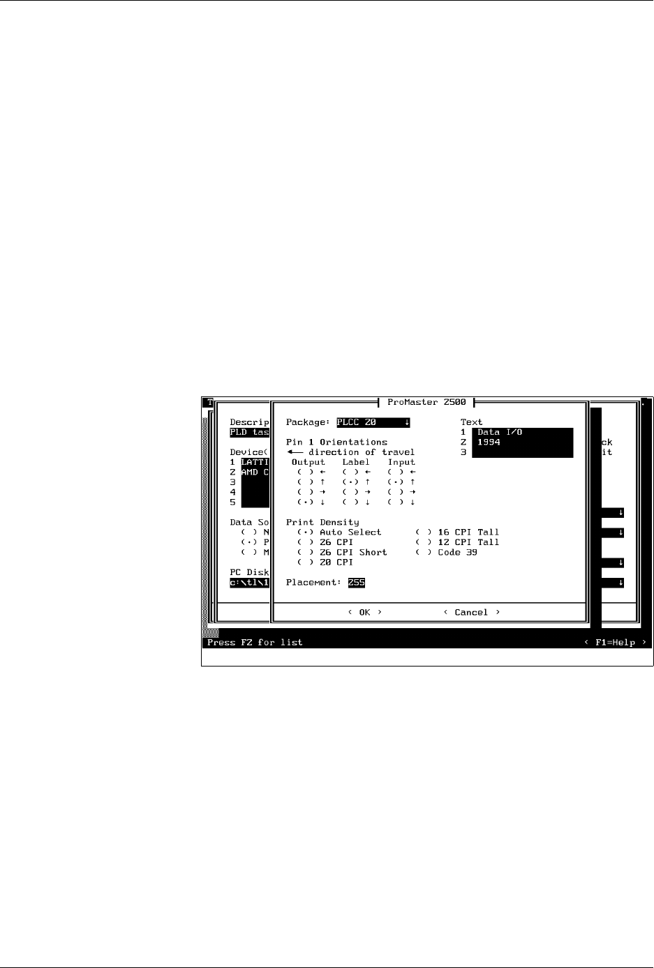
Selecting the Package Type
The
Package
field defines the device package type you will be
processing. Move the screen cursor to this field and press
F2
. TaskLink
displays a list of package and pin counts from 8-pin DIP to 84-pin PLCC
devices. The package type “
DIP 24-.3
” represents a 24-pin DIP device in a
300 mil. package width.
To select a new package type, move the screen cursor to the new type and
press
↵
.
Device Orientation: Pin 1
Press
T
AB
to move to the
Pin 1 Orientation
field. This parameter is
critical because it tells the 2500 where pin 1 on the device will be
positioned in the input track. The beam inserts the device into the
programming module with pin 1 always to the right, pointing toward the
input tube. The Task must accurately identify the position of pin 1 as the
devices are loaded in the input track so that the beam rotates and inserts
it in the programming module correctly.
Figure 3-6
ProMaster Dialog Box
Tasks and Kits
3-10 ProMaster 2500 User Manual
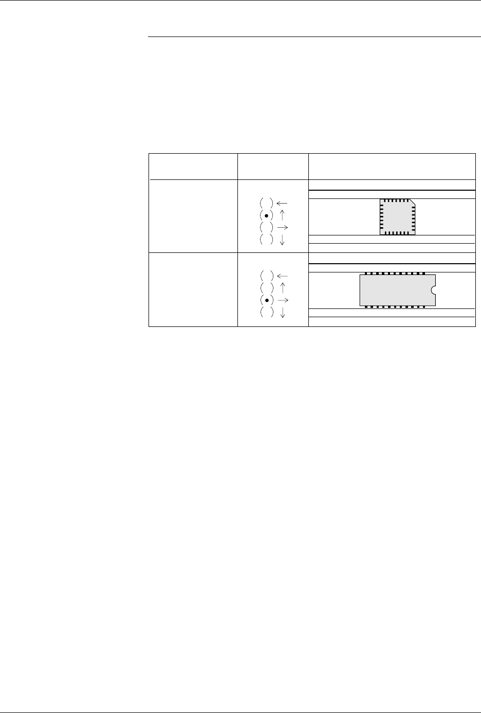
Note: Your company should establish a standard orientation for each device
package type (DIP, square PLCC, 32-pin PLCC, SOIC) so that all
operators insert devices correctly. All devices are inserted and handled
upside-down (also known as “dead bug”) on the 2500.
The arrows on the TaskLink screen point to the four sides of the device
(see Figure 3-7). Move the cursor using the
↑
and
↓
keys. Press
T
AB
when
you have the correct orientation highlighted for the Output
track.
TaskLink then prompts you for the Label and Input orientation fields.
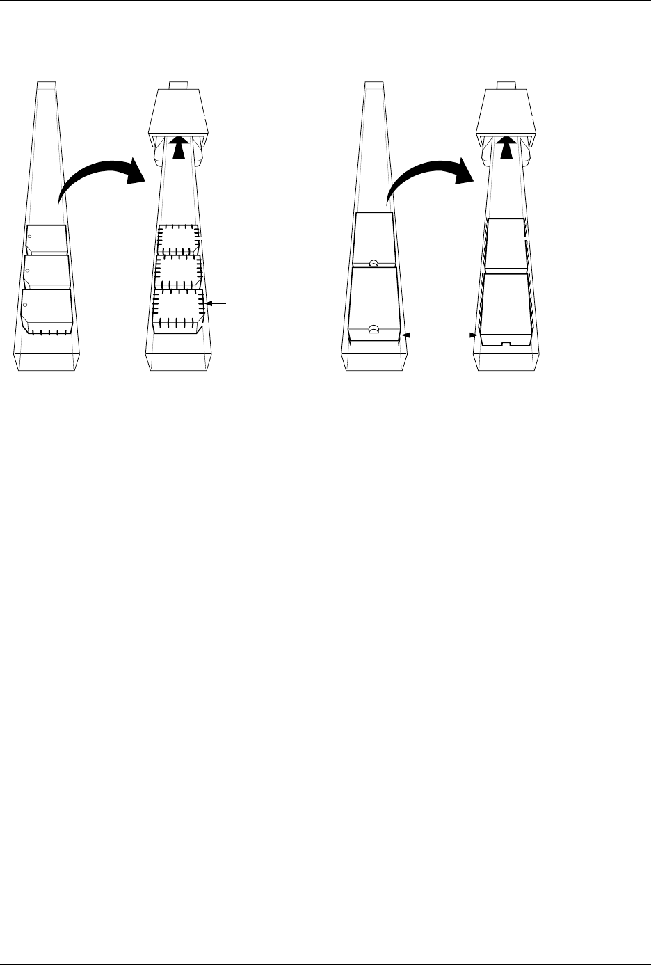
Install all devices upside-down in the 2500 so that their leads are pointing
toward the ceiling (dead bug). We recommend the following default
positions for pin 1 (see Figure 3-8):
• DIP devices: Pin 1 is to the right side, closest to the input tube.
• 32-pin PLCC devices: Pin 1 is to the right side, closest to the input
tube.
• Square PLCC devices: Pin 1 is pointing to the back of the 2500.
Figure 3-7
Selecting Orientation of Device
Pin 1 in the Input Tube Using
TaskLink
SQUARE PLCC
INPUT TUBE
INPUT
INPUT
TASKLINKPACKAGE
DIP, SOIC, and
32-PIN PLCC
TO 2500
TO 2500
1889-2
Tasks and Kits
ProMaster 2500 User Manual 3-11
Entering Label Text
Enter
Text
to appear on the label. The TaskLink screen may allow you to
enter more characters than will fit on the label you are using. The number
of characters per line varies, but labels are restricted to three printed lines
regardless of the label size or font selected.
TaskLink includes a set of unique character commands that you can use
to have TaskLink to print non-standard characters on your label. When
you enter the predefined sequence of characters in the text field on your
screen, TaskLink prints the special character they represent on the label.
These include:
• A time and date stamp is printed when you enter the
@
sign along
with an optional parameter (refer to the online help for a list of the
options).
• A copyright symbol is printed when a tilde (
~
) is entered.
• A serial number is printed when two or more
%
signs are entered.
• The sumcheck of RAM is printed when you enter at least two dollar
signs (
$
)
.
• The session ID is printed when two to eighteen carets (
^
) are entered.
The
Print Density
field allows you to select the font type in characters per
inch (CPI) that the labeler will use when printing your label. The 2500
defaults to
Auto Select
, which instructs the 2500 to select the optimal
character size based on the Package parameter and the amount of text
entered.
You may use the
Print Only
command in local mode to select the best
font for your label size and text length.
Figure 3-8
Recommended Device Orientation in Input Device
1854-3
NOTCHED
CORNER
INPUT TUBE
HOLDER
INPUT TUBE
HOLDER
TUBE INSERTED
WITH DEVICE
CONTACTS
FACING UP
TUBE INSERTED
WITH DEVICE
CONTACTS
FACING UP
SQUARE
PLCC
DEVICES
DIP/SOIC
DEVICES
PIN 1
PIN 1