2500_Users_Manual.pdf - 第141页
Operation ProM aster 25 00 User Manua l 4-27 Aligning a Device to a PLCC P rogramming Mo dule Whene ver yo u run a new Tas kLink Task or Kit using a PLCC de vice, the display on the 2500 prompts you to alig n the beam. F…

Operation
4-26 ProMaster 2500 User Manual
If you start a Task with an incorrect number in the Parts/tube field, press
STOP
and then
LOWER CASE
+
T
. Enter the correct number. Press
ENTER
and then
START
to continue running the Task.
This screen also indicates where TaskLink expects device pin 1 to be
located when the device is in the input track. This is critical for correct
device handling and insertion in the programming module socket. Make
certain that your device matches this positioning. Refer to page 4-22 for
more information on installing devices in the input tube holder.
The system automatically downloads the data file defined in your Task or
prompts you to insert a master device.
If the Task asks you to load RAM data from a master device, TaskLink
prompts you to insert the master device to be loaded. Place the device in
the input track, against the programming station stop guide. Be careful to
observe the correct orientation of pin 1.
Close the hood. The 2500 detects the device, picks it up, inserts it in the
programming module, and loads the device’s data into RAM.
After the load, the master device is set in the left device recess near the
labeler.

Operation
ProMaster 2500 User Manual 4-27
Aligning a Device to a PLCC Programming Module
Whenever you run a new TaskLink Task or Kit using a PLCC device, the
display on the 2500 prompts you to align the beam. Follow the procedure
below to adjust the position of the beam so that it picks the device at its
center and inserts the device into the programming module correctly.
Failure to perform the alignment and cleaning procedures may cause
premature wear of the module’s contacts and an eventual decrease in
programming yield.
Note: This alignment procedure assumes that the devices are
square PLCCs,
with pin 1 oriented toward the back of the input track
(away from
the front of the 2500). Alignment of rectangular, 32-pin PLCC devices is
described on page 4-32.
Align Beam to the Device
Follow these steps to align the beam to a device in the input track.
1. Insert a tube of devices into the input track and close the hood.
2. Start the new Task.
3. The beam positions itself over the first device and pauses. The 2500
displays:
PROGRAM/TEST ONLY
USE ARROW KEYS TO ALIGN BEAM WITH
DEVICE CENTER. PRESS [D] TO LOWER BEAM.
PRESS START TO CONTINUE.
Operation
4-28 ProMaster 2500 User Manual
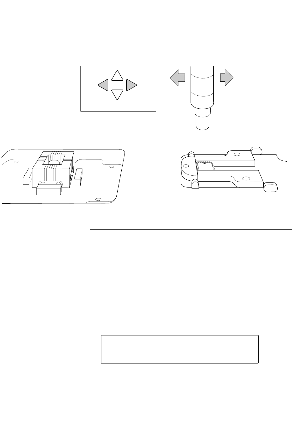
4. Press
←
and
→
to center the chuck over the device (left-to-right).
Pressing the arrow key once moves the beam one small step in that
direction.
Note: You can change beam alignment while a Task is running. When the beam
hesitates above the device, press
STOP
and use the front panel arrow keys.
5. Press and hold
D
on the 2500’s keyboard to lower the beam and
check the position of the chuck on the device. For a slower insertion,
lower the beam manually by pushing directly on the top of the beam
assembly, on either side of the beam’s limit bar (the limit bar is shown
in Figure 1-7).
Adjust the left-to-right position as necessary. When the beam is
centered, press
START
.
6. The beam picks up the device, rotates it 90
°
, moves it over the
programming module, and pauses before inserting the device in the
block. The 2500 displays:
Align Device to Module
7. Press
←
and
→
to center the device over the programming module
(left-to-right when you stand in front of the 2500).
Figure 4-22
Aligning Beam to the Device
PROGRAM/TEST ONLY
USE ARROW KEYS TO ALIGN DEVICE WITH
PROG. MODULE. PRESS [D] TO LOWER BEAM.
PRESS START TO CONTINUE.
FRONT PANEL ARROW KEYS
1857-1