2500_Users_Manual.pdf - 第130页
Operation 4-16 ProMa ster 25 00 U ser Ma nual Removing and Installing Chucks When you change to a new device package, select the appropriate chuck as shown in the chuck se lection chart (see Figu re 4-13) . CAUT ION: Chu…
Operation
ProMaster 2500 User Manual 4-15
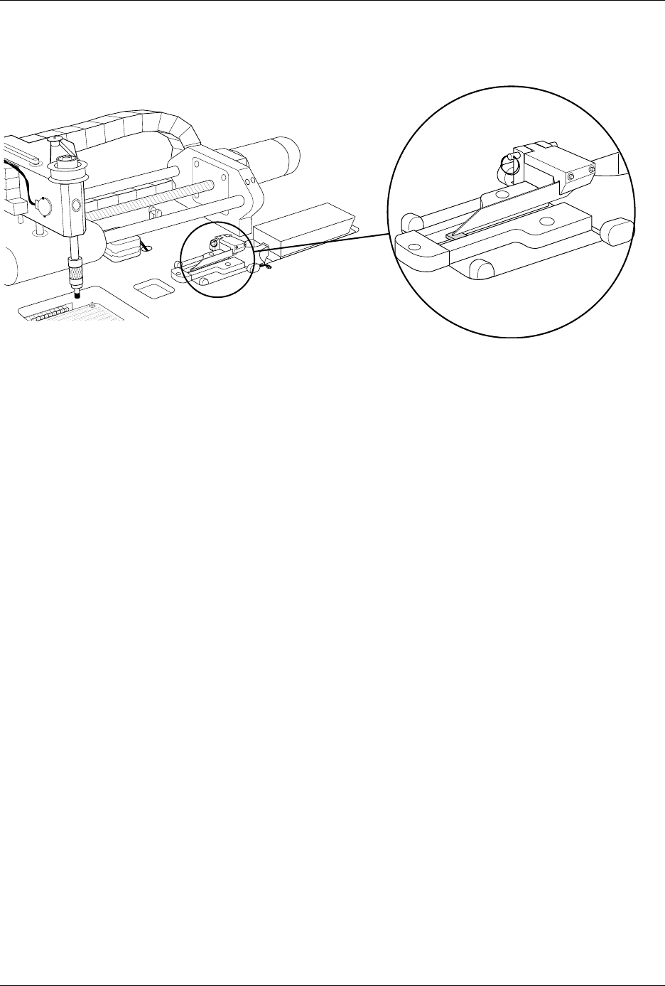
The device keeper bar assembly attaches to the mounting block with a pin
that has a detent ball on the tapered end and a handle ring on the other
end (see Figure 4-12). This allows the device keeper bar assembly to be
installed easily and when processing 150 mil SOIC devices, and removed
easily when processing other devices.
Before you start a Task, install the keeper bar assembly block to the
keeper bar mounting block, which should be already be attached to the
inside of the input track with two -inch hex screws.
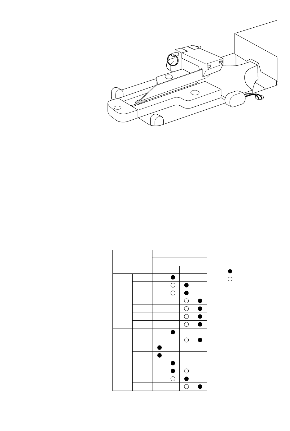
Attach the 8-pin 150-mil SOIC device keeper assembly by performing the
following procedure.
1. Insert the end of the keeper bar assembly block into the notch in the
top of the mounting block, with the keeper bar pointing to the left.
2. Insert the locking pin into the hole in the left side of the block, and
push it all the way in until you feel the detent ball click into place.
3. Swing the keeper bar toward you so that it is parallel to the input
track.
Figure 4-11
Closeup View of Input Track with 8-pin 150-mil Device Keeper Bar Assembly Installed
2500-1
332
⁄
Operation
4-16 ProMaster 2500 User Manual
Removing and
Installing Chucks
When you change to a new device package, select the appropriate chuck
as shown in the chuck selection chart (see Figure 4-13).
CAUTION: Chucks are released from the beam suddenly. If the beam is
positioned over the SPA pins or input track, the sudden
release may damage those areas.
Change the chuck with the beam directly over one of the two main plate
recesses. Keep the beam raised by holding it up with two fingers while
you use a downward pulling/twisting motion to remove the chuck. With
one hand on the beam for support, insert the new chuck by lifting it
straight up until it snaps into position.
Figure 4-12
8-pin 150-mil SOIC Device Keeper
Bar Assembly Mounted in the
Input Track
Figure 4-13
Chuck Selection Chart
2501-1
DEVICE
TYPE
PLCC
DIP
LMN
20-PIN
28-PIN
32-PIN
44-PIN
52-PIN
68-PIN
84-PIN
300 mil
600 mil
1850-3
Recommended
Alternate
SOIC 150 mil
220 mil
300 mil
330 mil
420 mil
500 mil
K
CHUCK
ProMaster 2500
Operation
ProMaster 2500 User Manual 4-17
Replacing a Chuck Tip
Remove the chuck from the beam and remove the old tip. The new tip
should extend slightly beyond the metal end of the chuck so an airtight
seal can be made. After it is on, lightly chalk the end of the tip before
processing devices. Chalking decreases the possibility of a device sticking
to the tip due to an accumulation of oils from being handled.
Adjusting High and
Low Air Pressure
Your external factory air input to the 2500 should be set so that it supplies
a constant 1.0 CFM at 80 PSI.
Note: To avoid unnecessary problems, be sure to provide the 2500 with a clean,
dry, externally filtered (10 micron) air supply.
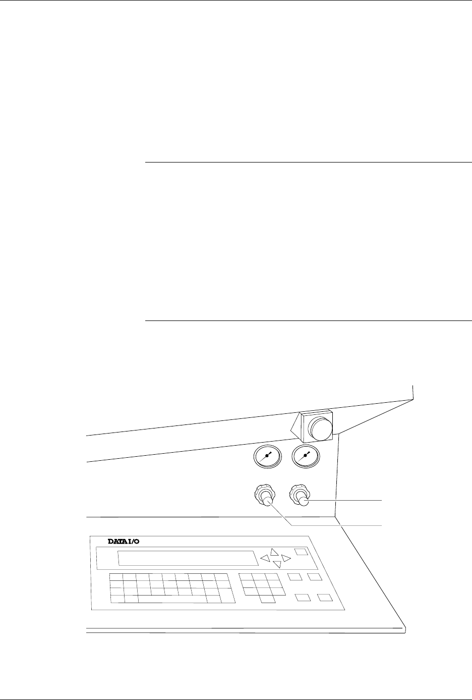
Adjust the high air pressure gauge on the 2500 to 75 PSI. When the
adjustment is correct, push the adjustment knob in toward the back of the
2500 to lock its position.
Set the low air pressure knob so that the gauge reads 30 PSI. It is normal
for this setting to fluctuate during operation, but it should not drop below
30 PSI or exceed 50 PSI. Make your final adjustments to the low pressure
setting after watching its fluctuation while the 2500 is processing devices.
See Figure 4-14. When the adjustment is correct, push the adjustment
knob in toward the back of the 2500 to lock its position.
Note: The ProMaster 2500’s high and low air pressure varies during operation;
this is normal and is not the symptom of a problem.
Figure 4-14
Adjusting High and Low Air Pressure
LOW PRESSURE
20-50 PSI
HIGH PRESSURE
65-85 PSI
A
J
S
SHIFT
B
K
T
DEL
C
L
U
D
M
V
E
N
W
F
O
X
SHIFT
G
P
Y
H
Q
Z
I
R
ENTER
1
4
7
2
5
8
3
6
9
0
LOWER
CASE
RESET
STOP
CAL
START
ON
1764-4
HIGH PRESSURE
ADJUSTMENT KNOB
LOW PRESSURE
ADJUSTMENT KNOB