2500_Users_Manual.pdf - 第55页
Insta llatio n and Se tup 2-12 ProMa ster 25 00 U ser Ma nual Installing t he Dot Matrix Printer Ribbo n Cassette Install the la beler ribbon cassette in the dot matrix printer by fol lowing this procedure (see Figure 2-…

Installation and Setup
ProMaster 2500 User Manual 2-11
8. Thread the label liner across the platen and lower the application
plate to hold it in position.
9. Route the liner to the left side of roller
E
and to the right of roller
F
.
Allow the remaining liner to drape to the left of knob
G
.
10. Move roller
F
to the right until it snaps into position.
Note: To ensure correct label printing and application, make sure both pinch
rollers (
B
and
F
) are fully engaged.
Calibrating Labels
At certain times, you must calibrate the labels so that the 2500 can
correctly print and apply them to devices. During the label calibration
process, the ADC (label detection) optic reads and assigns a value to the
amount of light passing through the label when it is blocking the optic.
You can view and adjust this ADC optic value from the 2500’s optics
diagnostics menu (refer to page 5-34).
You must calibrate labels whenever you:
• Change the labels
• Change the ribbon
• Advance the labels by running the label drive motor test, turning the
label advance knob, or pulling the labels forward by hand
• Adjust the ADC optic value
To calibrate labels, do the following:
1. Place your finger next to the press bearings to “catch” the two or
three labels that are advanced during the calibration process.
2. Press
CAL
on the 2500’s keyboard.
3. When the labels stop advancing, calibration is complete.
Installation and Setup
2-12 ProMaster 2500 User Manual
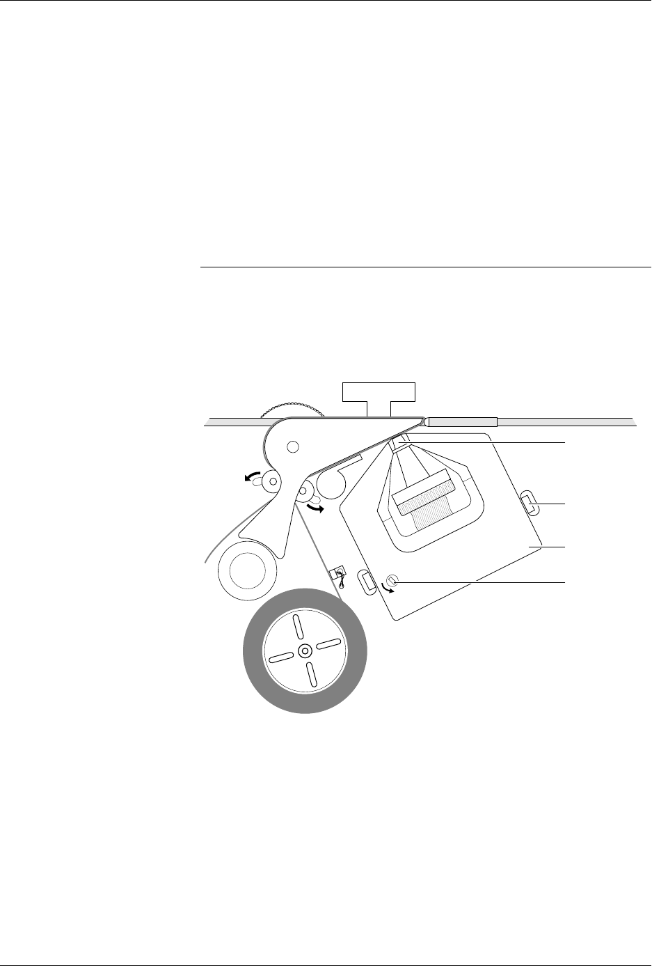
Installing the Dot Matrix
Printer Ribbon Cassette
Install the labeler ribbon cassette in the dot matrix printer by following
this procedure (see Figure 2-10):
1. Rotate the knob on the new cassette in the direction indicated by the
arrow (counter-clockwise) to pull the ribbon taut.
2. Guide the new cassette so the ribbon fits between the print head and
the platen.
3. With the ribbon now partially in place over the print head, slowly
turn the cassette knob while applying gentle pressure on the cassette
until it drops into place on the ribbon spline drive. The spline drive is
located on the labeler directly behind the ribbon advance knob.
Note: You will have to turn the ribbon advance knob slightly until the slot on
the back of the cassette aligns with the spline drive.
4. Ensure that the ribbon is in place by lightly pulling on it. It should not
come off the clips.
5. Calibrate the labels (see page 2-10).
Figure 2-10
Installing the Labeler Ribbon
Cassette in the Dot Matrix Printer
1852-2
PRINT HEAD
SPRING CLIP
(1 of 2)
RIBBON
ADVANCE
KNOB
RIBBON
CASSETTE

Installation and Setup
ProMaster 2500 User Manual 2-13
Setting Up the
Thermal Printer
Before labels can be printed and applied to processed devices, the label
and ribbon material must first be loaded. The following sections cover
the correct procedures for loading and calibrating labels and loading a
new ribbon and repairing a torn ribbon.
Loading Labels
Threading labels on the thermal labeler is similar to threading labels on
the dot matrix labeler (see Figure 2-11). The major difference on the
thermal printer is that the retractable rollers (platen pinch and label pinch
rollers) snap back into position if you release them. On the dot matrix
labeler, the rollers remain in the open position.
Note: Do not tighten the label roll on its core. The roll is intentionally loose so
the combination of high temperature and humidity do not cause the labels
to peel incorrectly.
Follow this procedure to load a new roll of labels.
1. Push the label pinch roller and the platen pinch rollers into their
retracted positions away from the platen.
2. Remove the magnetic cover from the label roll.
3. Install the new label roll on the label supply hub so that the leader
comes off from the right side of the hub (see Figure 2-11).
4. Mount the magnetic cover over the label roll to hold the labels in
place.
5. Prepare the label path by raising the application plate and retracting
the platen pinch and label pinch rollers.
6. Thread about 2 feet (60 cm) of label liner around the left side of the
label alignment roller and through the gap between the application
plate and the output track. Lay the liner along the output track for the
time being.
7. Position the label liner on the underside of the platen and guide the
platen pinch roller back into its operating position against the platen
to hold the liner in place.
8. Thread the liner between the ADC optic and the platen, and then
between the print head and the platen.
9. Make sure that the label liner is flat against the underside of the
platen.
10. Feed the liner back over the top of the platen and through the gap
between the platen and the track.
11. Thread it between the label drive roller and the label pinch roller (see
Figure 2-11).
12. Thread the liner between it and the drive roller. Guide the spring-
loaded pinch roller back into its operating position against the drive
roller. Make certain that there is no slack in the liner.
13. Lower the label application plate.
This completes the installation procedure. Be sure to calibrate the labels
as described in the next section before attempting to label devices.