2500_Users_Manual.pdf - 第278页
Repair and Repl acement Procedures 7-34 ProMa ster 25 00 U ser Ma nual 9. When the co ntact set is in positio n, insert and tighten th e two hex screws that hold it in place. The programm ing block cons ists of two piece…
Repair and Replacement Procedures
ProMaster 2500 User Manual 7-33
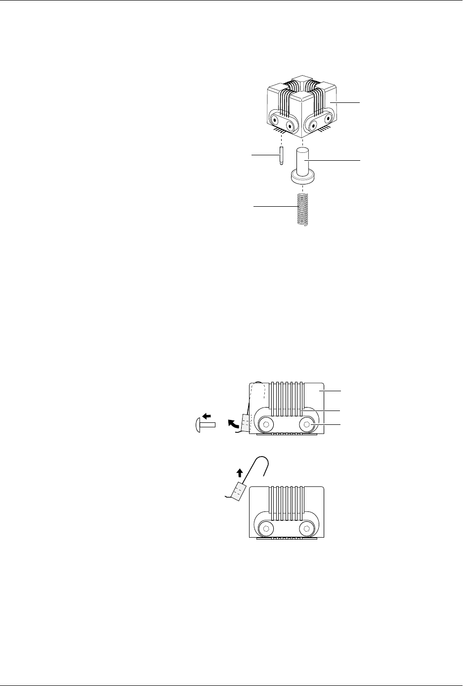
4. The device ejector pin and ejector spring are loose and will drop out
into your hand when you turn the block upright (see Figure 7-24). Set
these aside; you will reinstall them later.
5. Use a 1/16-inch hex driver to remove the two screws holding the
contact set in place.
6. Gently pivot the base of the contact set out from the programming
block and then lift the set straight up (see Figure 7-25).
7. Wipe the new contacts with a DeoxIT pen from the top of each
contact lead to its end (the portion of the contact that touches the
device’s leads). Remove any excess DeoxIT with a clean, dry cotton
swab. Preparing the leads in this way ensures that they are clean and
well lubricated.
8. Insert the new contact set into the programming block. Hold the set
at an angle and gently feed the tips of the contact set into the holes in
the top of the programming block.
Make certain that all the tips in the set have seated into their holes
before swinging the set’s base into position along the block. Failure to
insert all the tips in their correct positions could result in damage to
the contacts.
Figure 7-24
Removing the Device Ejector Pin
and Spring
Figure 7-25
Removing the Contact Set
1681-2
DEVICE EJECTOR PIN
DEVICE EJECTOR SPRING
PROGRAMMING
BLOCK ASSEMBLY
GOLD PIN
1668-1
CONTACT SET
PROGRAMMING BLOCK
ASSEMBLY
SCREW (1 of 2
per Contact Set)

Repair and Replacement Procedures
7-34 ProMaster 2500 User Manual
9. When the contact set is in position, insert and tighten the two hex
screws that hold it in place.The programming block consists of two
pieces: a top and a base. The contact set screws hold the top and base
together.
Keep at least one contact set installed so the top does not separate
from the base. If the top and base come apart, refer to page 7-38, step
9 for instructions on reassembling the programming block.
10. Replace the worn contact sets on the remaining three sides.
Note: Replace all four contact sets. Mixing new sets with old will make it
difficult to determine which of the sets is causing a problem.
11. Turn the assembled programming block upside-down and insert the
device ejector pin and its spring into the programming block.
CAUTION: The capacitor configuration blocks should not be installed
on the board when the programming block is being inserted
on the programming module board. Pins on one of the
contact sets might hook on the block and become bent or
damaged.
12. Using the block alignment pins as guides, carefully slide the board
and block together.
13. Install the two hex screws mounting the block to the board.
14. Install the configuration blocks for the next device to be
programmed.Refer to page 4-7 for more information on configuring
the module.
15. Check the operation of the programming module using a device type
that usually gives you high yields.
Replacing Pins on a
SOIC Programming
Module
Use the following procedure to replace the spring-loaded pins on any of
the SOIC programming modules.
CAUTION: To avoid possible damage to the system components, this
procedure should be performed only by a qualified service
technician.
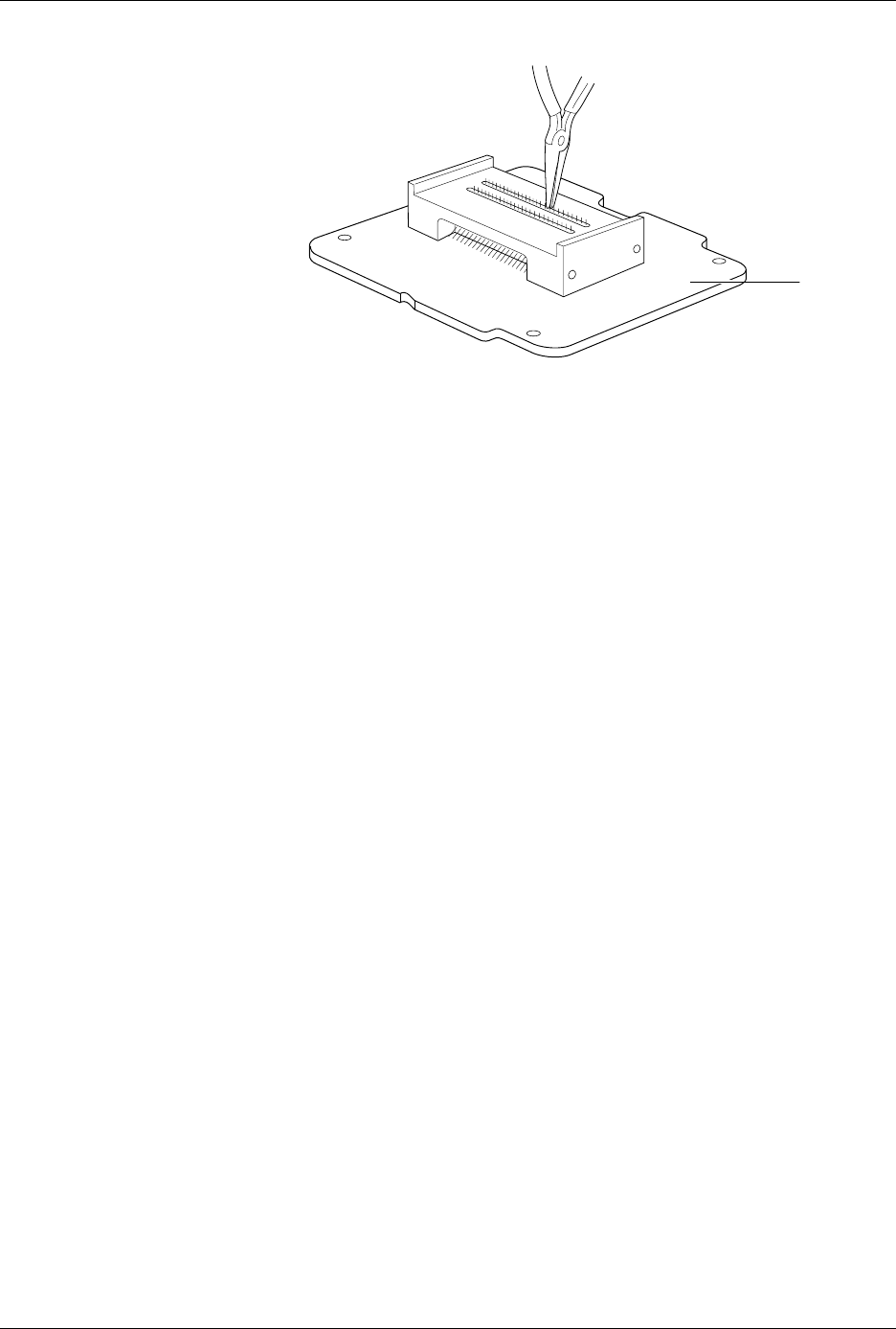
1. Set the module on a flat surface and grasp the defective pin with a
pair of needle nose pliers. Pull the pin straight up and out of the
programming block (see Figure 7-26).
Repair and Replacement Procedures
ProMaster 2500 User Manual 7-35
2. Using the needle nose pliers, insert the replacement pin in the same
hole in the block.
3. To ensure that the pin is seated correctly, use the pliers (or flat end of
a flat-blade screwdriver) to press down on the spring-loaded pin
until it is flush with the block. Do not use any object to push the pin
farther down the hole.
4. Continue replacing any other questionable pins, and then test the
module by running a device-related operation on the system.
Replacing the Pin
Insulation Block
After a high number of device insertions in the programming module, the
holes in the pin insulation block may become enlarged or elongated. This
increase in hole size may eventually allow too much movement of the
module pins while a device is being inserted, resulting in a higher
number of continuity test and device programming errors. If you
experience a gradual increase in these failures, examine the insulation
block for enlarged pin holes.
If you determine that the pin insulation block needs to be replaced,
perform the following steps.
1. Remove all module pins (gold spring-loaded pins) from both pin
insulating blocks.
2. Turn the module upside-down and remove the two recessed Phillips
screws that hold the programming block to the circuit board.
After the screws have been removed, the programming block will
still be held to the board by the physical tension caused by the two
alignment pins.
3. Pull the board straight up and away from the block.
4. Remove both pin insulation blocks from the programming block with
a pair of needle-nose pliers.
5. Insert two new pin insulation blocks.
Figure 7-26
Replacing the Defective Pins
1930-1
PRINTED
CIRCUIT
BOARD