2500_Users_Manual.pdf - 第220页
Preven tive Maint enance 5-66 ProMa ster 25 00 U ser Ma nual 5. To perform a coarse track w idth adjus tment, use a 3/32-inch hex wrench to loosen the four set screws in the cable pinch block (see Figure 5-29). Use calip…
Preventive Maintenance
ProMaster 2500 User Manual 5-65
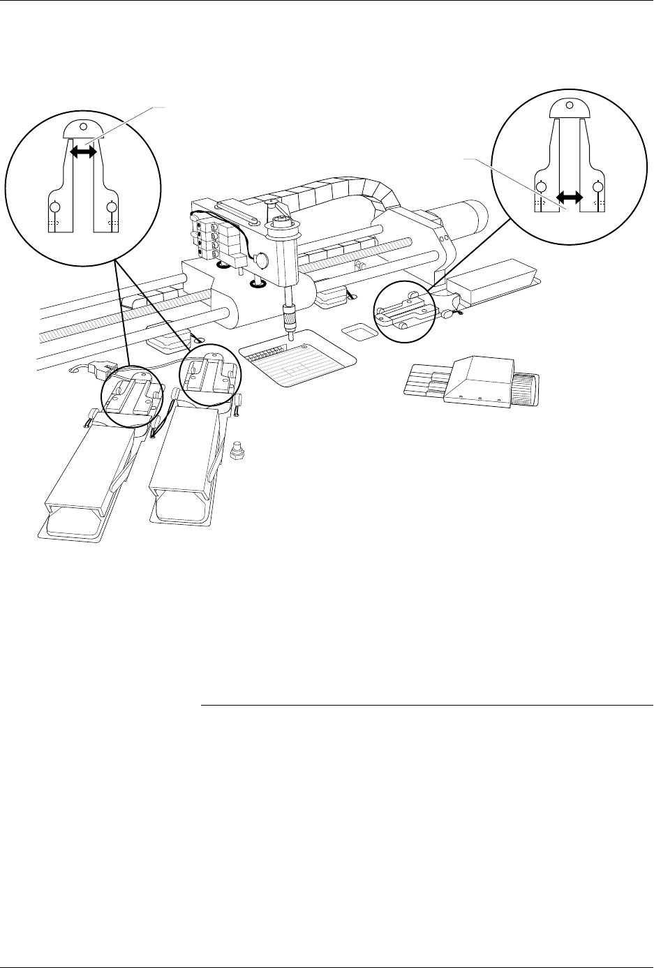
Adjusting the Track Width
Cables
All three tracks should have the same track width and be adjusted
equally. If one of the tracks is out of adjustment with the others, you may
have to perform the track width adjustment procedure. To perform the
track adjustment procedure, follow the steps below.
Note: Under normal circumstances the tracks should stay in adjustment and
you should not have to perform this procedure. Make sure you have
correctly determined that one of the tracks is out of adjustment before you
proceed.
1. Turn off the 2500 and remove the power cord.
2. Loosen the two screws in the corners of the main plate.
3. Lift the main plate until it stops in the fully upright position.
4. To perform a fine track width adjustment, use an adjustable wrench
to tighten or loosen one of the track adjustment nuts (see Figure 5-29).
Turn the nut clockwise to make the track wider or counter-clockwise
to make the track narrower.
Figure 5-28
Input and Output Track Funnel Adjustment
2284-2
OUTPUT TRACK
TRACK ENTRANCE
(Make wider by .010")
TRACK ENTRANCE
(Make wider by .010")
INPUT TRACK
Preventive Maintenance
5-66 ProMaster 2500 User Manual
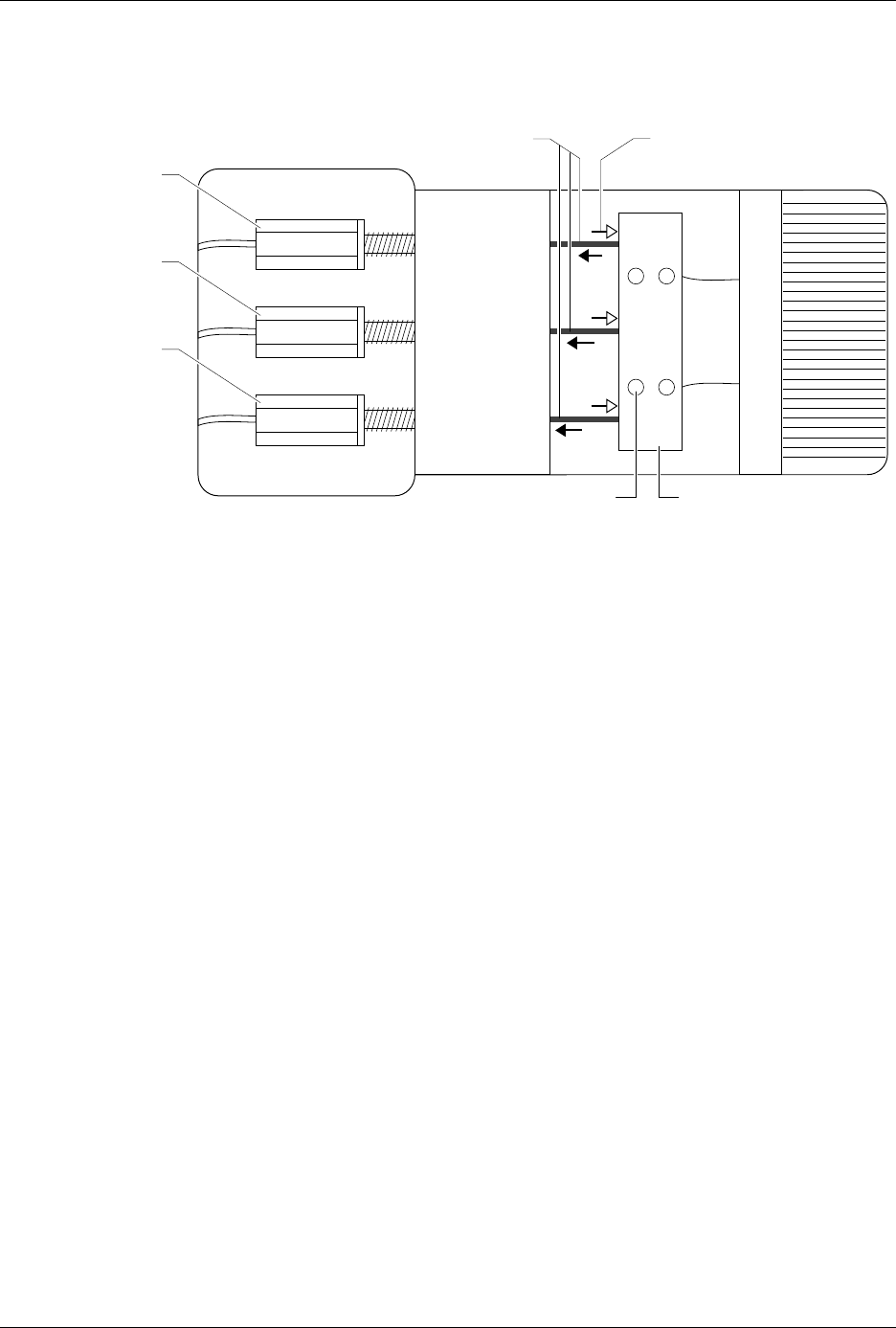
5. To perform a coarse track width adjustment, use a 3/32-inch hex
wrench to loosen the four set screws in the cable pinch block (see
Figure 5-29). Use calipers or a device to set a constant width for all
three track sections. Use a needle-nose pliers to pull one of the cables
away from the adjustment nuts to make the track wider, or push the
cable toward the adjustment nuts to make the track narrower.
6. Tighten the four set screws to lock the cable(s) in their new position.
Recheck the track width by opening the track to its widest setting
and then closing it down to the width used in step 5.
7. Apply a drop of silicone-based glue (such as RTV™) where the cable
enters the cable pinch block.
Figure 5-29
Adjusting the Track Width Cables
2285-1
PULLING THE CABLES
WILL WIDEN THE TRACK
PUSHING THESE CABLES
WILL NARROW THE TRACK
or
INPUT TRACK *
OUTPUT TRACK 1 *
(Right track)
OUTPUT TRACK 2 *
(Left track)
Turn clockwise to make
tracks wider
Turn counter-clockwise
to make tracks narrower
*
SET SCREW (1 of 4)
CABLE PINCH BLOCK

Preventive Maintenance
ProMaster 2500 User Manual 5-67
Maintenance Intervals
Interval Component 2500 Operator 2500 Service
Every Day
Programming module
Track
Beam chuck tips
Optic holes
Beam-to-programming module
alignment
Label path
Clean with air
Clean
Inspect/clean
Inspect/clean
Inspect
Clean
–
–
–
–
–
–
Every Week
Programming module contacts – Clean with DeoxIT
Every Month
(based on 40,000
devices/month)
Dust guards
Operator’s maintenance
(see page 5-55)
Keyboard and display
Beam chuck tips
Labeler ribbon
Label platen area
Programming module contacts
Label print quality
Label platen area
Thermal print head
Clean
–
–
Clean/replace
–
–
–
–
–
–
–
Verify process
Clean
–
Inspect/replace
Inspect/clean
Inspect/replace
Check
Inspect/clean
Clean
Every 6 Months
Beam lead screw
Beam vacuum generator filters
Beam limit bumper feet
DIP programming module contacts
Beam head shafts
–
–
–
–
–
Clean/lubricate
Clean/replace
Replace
Inspect/replace
Inspect/lubricate
Every 2 Years
Print head
Labeler ribbon clips
–
–
Replace
Replace