2500_Users_Manual.pdf - 第207页
Preventi ve Mai nten ance ProM aster 25 00 User Manua l 5-53 4. Check the +15 reference by reading pin 24 (+ 15V) on the connector block (see Figure 5-14). The +15V s ignal should read between the mini mum and maximum va…
Preventive Maintenance
5-52 ProMaster 2500 User Manual
2. Check the 8 MHz programming electronics clock frequency by
placing the ground probe of your scope (or frequency counter) on
pin 1 (ground) and the input probe on pin 28 (see Figure 5-22).
The clock frequency should read between the minimum and
maximum values shown below:
3. Check the +10V precision reference by reading pin 78 (+10V) using
your digital multimeter (see Figure 5-14). The +10V signal should
read between the minimum and maximum values shown below:
Minimum Nominal Maximum
7.999 MHz 8.000 MHz 8.001 MHz
Minimum Nominal Maximum
+9.090V 10.000V 10.010V
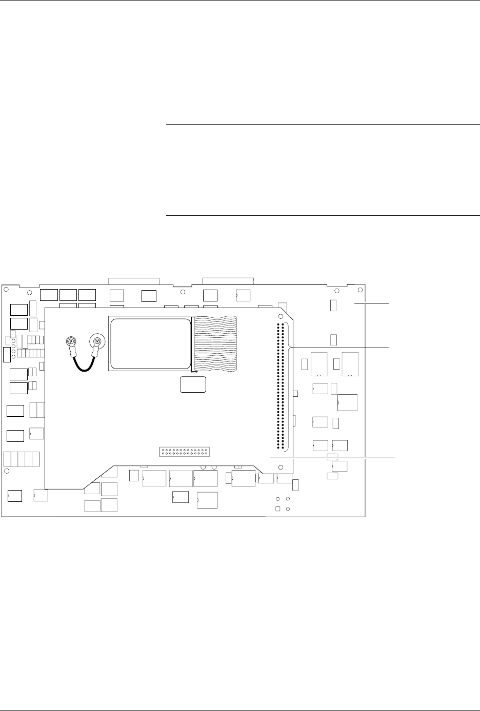
Figure 5-21
Position of the 78-pin Connector on the Mass Storage Module
2142-1
WAVEFORM BOARD
78-PIN CONNECTOR
MASS STORAGE
MODULE
Preventive Maintenance
ProMaster 2500 User Manual 5-53
4. Check the +15 reference by reading pin 24 (+15V) on the connector
block (see Figure 5-14). The +15V signal should read between the
minimum and maximum values shown below:
This completes the performance verification for the programming
electronics assembly.
If any of the measurements described above are outside the specified
ranges, contact Data I/O Customer Support as listed in the Preface.
Running the Self-test
You cannot access the self-test command from TaskLink’s operator mode.
To perform a self-test you must be in TaskLink’s administrator mode. To
start this self-test, perform the following steps:
1. From the DOS prompt, start TaskLink in administrator mode by
entering
tl a
on your PC keyboard at the DOS prompt. If you are already running
TaskLink, exit TaskLink and restart it in administrator mode.
2. Select
Programmer Interface
from the
Utilities
menu.
3. Check the programming module to verify that no device is installed.
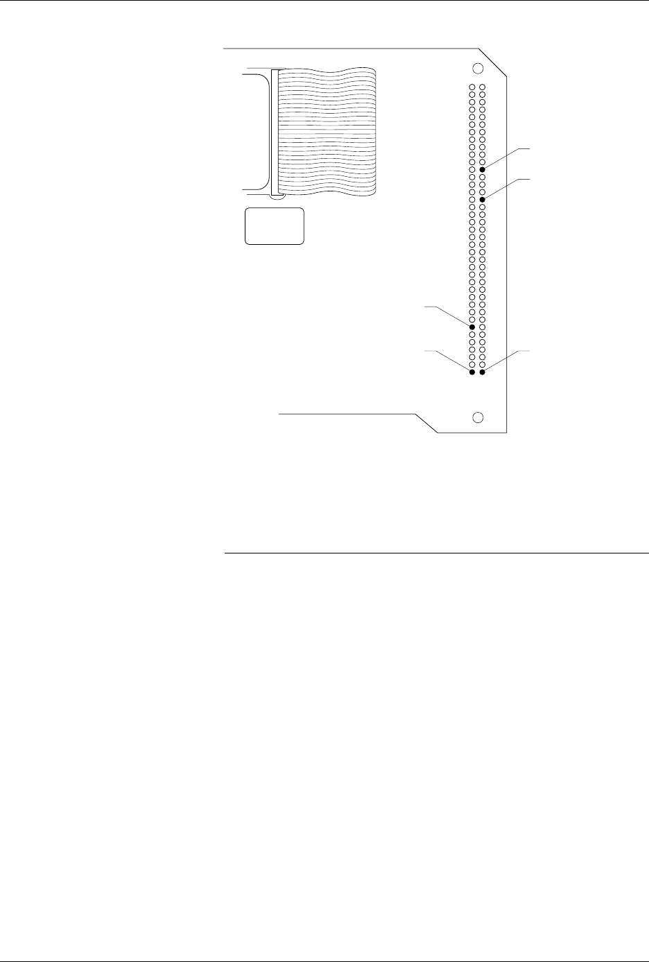
Figure 5-22
Test Points on the MSM 78-pin
Connector
Minimum Nominal Maximum
+14.25V +15.00V +15.75V
178
3940
PIN 28 (8MHz)
PIN 24 (+15V)
PIN 1 (Ground)PIN 78 (+10V)
PIN 72 (Plugged)
2143-1

Preventive Maintenance
5-54 ProMaster 2500 User Manual
4. Press
F1
. If you are prompted to select a new terminal type, press
↵
to
accept the default.
5. Select
M
(More Commands) and
S
(Self-test) to get to the Self-test
screen.
6. Select the One Pass mode to perform all the displayed tests once.
7. Move the cursor to the Test Mode field and press
S
PACE
. You may
stop the test by pressing
C
TRL
+
Z
. There may be a delay before the
system responds to the C
TRL
-Z if you are testing system RAM.
CAUTION: Executing the System RAM test or the User RAM test erases
all data in RAM.
8. To test all hardware, move the cursor to the
Perform All Tests
prompt and press
↵
. To test a particular item, move the cursor to the
desired test and press
↵
.
One of the following four characters will appear next to each test to
indicate the status of that test:
? Untested
Pass
Fail
_ Not Installed
When testing begins, a question mark (
?
) appears next to the untested
areas. As each test completes, either
PASS
or
FAIL
appears next to the
test name to show the results of that test. The “
?
” may be displayed on
some tests if the programming electronics has failed an earlier test. In this
case the “
?
” means that this item was not tested and will not run until the
earlier failure has been corrected.
Note: When you abort a test, a status of
????
is displayed, and if you try to run
TaskLink, the message
Programming hardware has not passed
self test
is displayed.
A hyphen (–) indicates that an item is not installed on your ProMaster
2500 system.
While a test is being performed, a rotating action symbol and a status
message are displayed in the upper, left corner of the TaskLink screen.
Tests are performed in the following order:
1.
Calibration of the supplies
(on the controller/waveform board)
2.
Pin control unit test
(on the controller/waveform board)
3.
EPROM
(on the controller/waveform board)
4.
Serial ports
(on the controller/waveform board)
5.
System RAM
(on the controller/waveform board)
6.
User RAM
(on the controller/waveform board)
7.
Disk drive
8.
Programming module/relays
(on the pin driver boards)