2500_Users_Manual.pdf - 第191页
Preventi ve Mai nten ance ProM aster 25 00 User Manua l 5-37 Figure 5-14 Thermal Printer, Fr ont View, Showing the ADC Label Optic 2303-1 LABEL DRIVE ROLLER (hidden) LABEL PINCH ROLLER LABEL ADVANCE KNOB LABEL ALIGNMENT …

Preventive Maintenance
5-36 ProMaster 2500 User Manual
Always calibrate the labels (refer to the procedure on page 5-25) after
performing either one of the following operations:
• Installing a new roll of labels
• Changing the ribbon
• Adjusting the ADC reference value
• Manually moving the labels
To check and manually adjust the ADC value, follow the steps below:
1. Put the 2500 in local mode.
2. Select OPTIC TEST from the DIAGNOSTIC MENU and load labels.
3. Locate the ADC optic and ensure that a label is blocking the optic’s
beam to obtain the highest ADC optic value. The 2500 should
display:
4. If a label is not blocking the ADC optic, slowly turn the label advance
knob in the counterclockwise direction to advance the liner. The
value on the display fluctuates until the label blocks the optic and the
highest value appears. Do not begin the adjustment procedure until
you are certain that a label is blocking the optic.
If the ADC value is not in the range of 190 to 200, press
LOWER CASE
+
A
while in the Optic diagnostics menu. Press
↑
or
↓
until the displayed value reaches 200.
5. Turn the label advance knob until the ADC optic is reading only the
liner (it should read between 120 and 170, if the liner is opaque). The
liner reading is not adjustable because the range is variable.
Return to the Main Menu by pressing
RESET
. Press
CAL
to have the 2500
run a label calibration to adjust to the new setting.
Note: Adjust the ADC reference value for the label material you are using. If
you are using both Kapton and thermal poly label material, adjust the
ADC reference value for Kapton. If you are using thermal poly label
material exclusively, you may need to make only minor adjustments.
OPTIC TEST - ADC = 200 - VAC = 23
11100000001111101111111100 ENC = 13107
| | | | | U15 REV 1.00
5 10 15 20 25 U43 REV 1.00
Preventive Maintenance
ProMaster 2500 User Manual 5-37
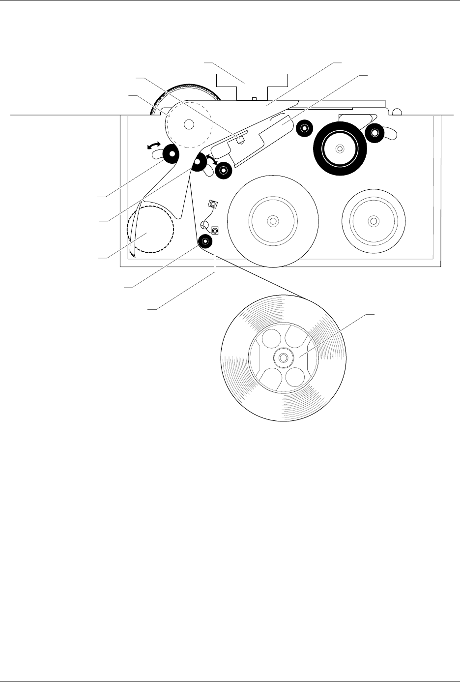
Figure 5-14
Thermal Printer, Front View, Showing the ADC Label Optic
2303-1
LABEL DRIVE ROLLER (hidden)
LABEL PINCH ROLLER
LABEL ADVANCE KNOB
LABEL ALIGNMENT ROLLER
LABEL DETECTION OPTIC
LABEL ROLL
(cover removed)
APPLICATION PLATE (raised)
PLATEN
PRINT HEAD
(retracted position)
LABEL ADC OPTIC
PLATEN PINCH ROLLER
Preventive Maintenance
5-38 ProMaster 2500 User Manual
Solenoid Test
Run this test to evaluate the operation of the solenoids.
Note: You can also manually test each solenoid by pressing on the actuator
button on the side of each solenoid.
WARNING:Performing these diagnostic procedures will expose you to
harmful high voltage. Only a service technician trained on
electromechanical equipment should perform the
diagnostic tests described in this manual. If you are not a
service technician who has been trained on the 2500, do
not lift the main plate as described in some of the
diagnostic test procedures.
From the Diagnostics menu, press
2
. The 2500 displays:
When you test a solenoid, confirm that the action it controls is taking
place. If it is not, check the LED mounted directly on the solenoid to see if
it is illuminated. Refer to Figures 5-15 and 5-16 for the location of the
solenoids. An illuminated LED on the solenoid indicates that it is active.
Each solenoid is turned on and off by a control circuit on the handler
controller board.
PRESS NUMBER OF SOLENOID, E TO EXIT
1 - UNUSED 4 - BEAM UP 7 - VACUUM
2 - BLOWER 5 - BLOWER OFF 8 - CLAMP
3 - CUT OFF 6 - HIGH PRESSURE
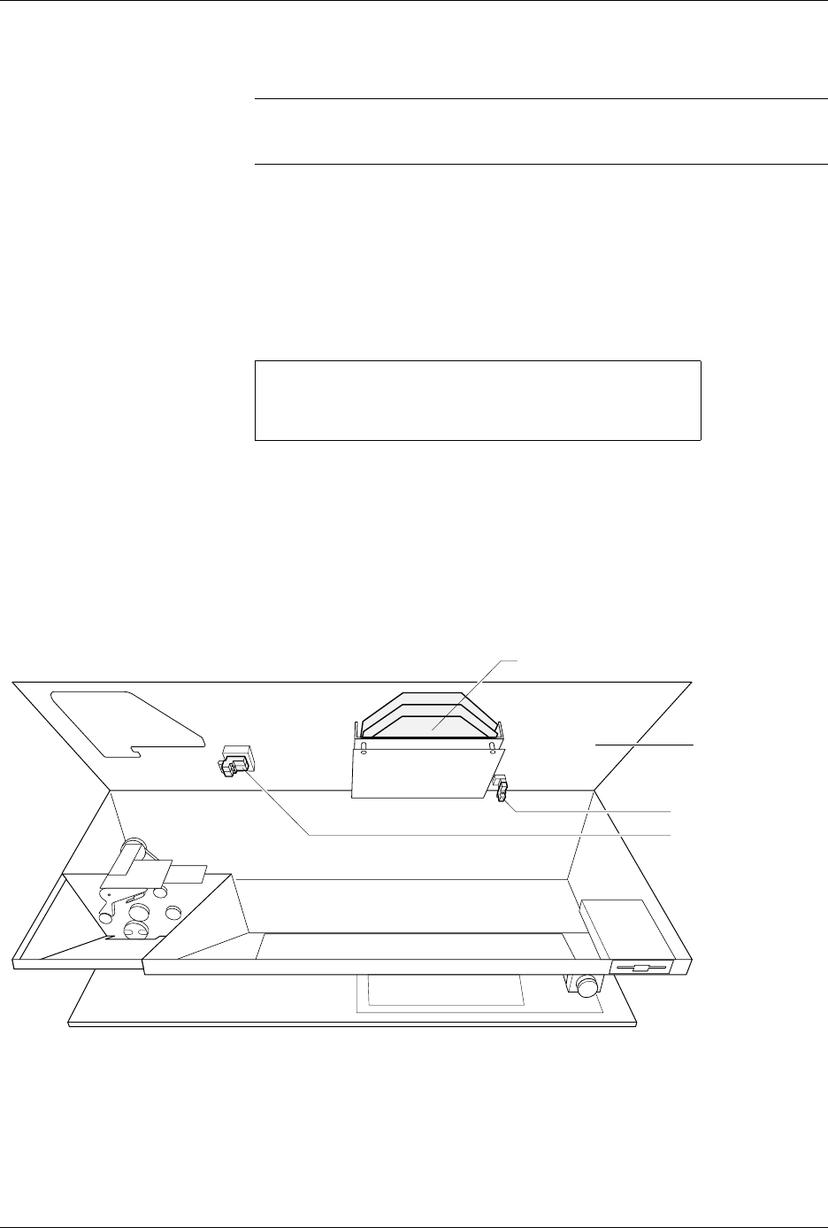
Figure 5-15
Locations of the Solenoids Under the Main Plate
1949-2
SOLENOIDS (2, 3)
MAIN PLATE
(under side)
PROGRAMMING ELECTRONICS ASSEMBLY
SOLENOID (8)